
Spinal orthosis

a spine and orthosis technology, applied in the field of spine orthosis, can solve the problems of little, if any, improvement in spine alignment when applied, design limitations and shortcomings, and limitations in the degree to which orthoses can improve alignmen

Active Publication Date: 2020-10-27
HAWKINS MICHAEL BROWNING
View PDF13 Cites 2 Cited by
  • Summary
  • Abstract
  • Description
  • Claims
  • Application Information

AI Technical Summary

Benefits of technology

The present invention is a spinal orthosis that includes a brace shell and a strap. The strap extends inside the brace shell and wraps around it. The strap has two ends, one of which attaches to the brace shell and the other of which is detachable. When tensioned, the strap pushes the brace shell closed, improving its fit and comfort. The spinal orthosis of this invention provides better support and stability to the wearer's spine.

Problems solved by technology

Some past designs of this type are merely supportive and provide little, if any, improvement in spine alignment when applied.
However, these designs have limitations and shortcomings.
These orthoses are limited in the degree to which they can improve alignment due to their static characteristics.
There are upper limits to the degree this type of orthosis can be further tightened during daily wear due to the need for expansion during the wearer's inhalation phase of the respiratory cycle.
During points in their respiratory cycle when their torso dimensions are smaller, the corrective forces reduce and alignment is lost.
However, a static spinal orthosis is unable to take advantage of this occurrence as it is not able to provide corrective forces across any range of movement or change in position of the wearer's torso.
They often require relatively many components and as a result are usually more bulky and are more visually apparent under the wearer's clothing.
Additionally, the cost of the additional, more sophisticated components and the additional time of manufacture make this type of brace in the prior art costly to manufacture.
Orthoses that comprise metal or rigid structural components such as a rod of relatively significant size have become an object of distaste for wearers and, in modern times, a reason for which many child and adolescent wearers will reject the use of a brace and become non-compliant.
This is one reason why the dynamic braces in the prior art are not popular in many clinical settings in our current society.
This design limits the extent to which the system can resist torsional and bending moments placed on it by the torso of a wearer with a misaligned spine and thus limits the degree to which this type of orthoses can correctively align a wearer's spine.
Additionally, U.S. Pat. No. 7,967,767 is labelled as “dynamic”; however, this spinal orthosis contains no mechanism to continually apply corrective forces to a wearer throughout movement and change in wearer position without further adjustment.
This design lacks the ability to adjust to the positions of the user while wearing the orthosis without a third party manually adjusting the dimensions of the brace, and therefore lacks the essentials of a truly dynamic brace.
I have observed that it is not possible to apply forces to the external surface of the human body in a defined and predetermined vector sufficient to align a wearer's spine relying substantially on supple, or soft textile based woven materials.
Tensioning the fabric of this type of orthosis in an attempt to create corrective forces on the spine, unfortunately, produces a compressive force on the spine through the wearer's shoulder complex and upper ribs over which the orthosis is wrapped.
This compressive force is counterproductive to the alignment of a scoliotic spine.
It is also apparent through clinical observation that orthoses comprised substantially of flexible material substantially conform to the deformities on the body's surface that result from the spinal deformities, and are ineffective at aligning the scoliotic spine and improving postural deformities that result therefrom.
This presents another point at which wearing an orthosis affects a wearer's regular routine and preferences and therefore deters compliance.
This type of design sacrifices a significant amount of stiffness in resistance to torsional forces created by the rotational deformity of scoliosis.
The aspect of each shell component in the area of each shell's connection to the rod experiences a significant amount of deformation when attempting to resist the torsion and bending moments placed on the system by the wearer and renders the orthosis ineffective.
This approach provides no method of applying direct contact to areas of the body most proximate to a lower thoracic or upper lumbar curve apex.
With relatively many straps, these orthoses take a relatively long time to don.

Method used


Image

  • Spinal orthosis
  • Spinal orthosis
  • Spinal orthosis

Examples


Embodiment Construction

A. Advantages

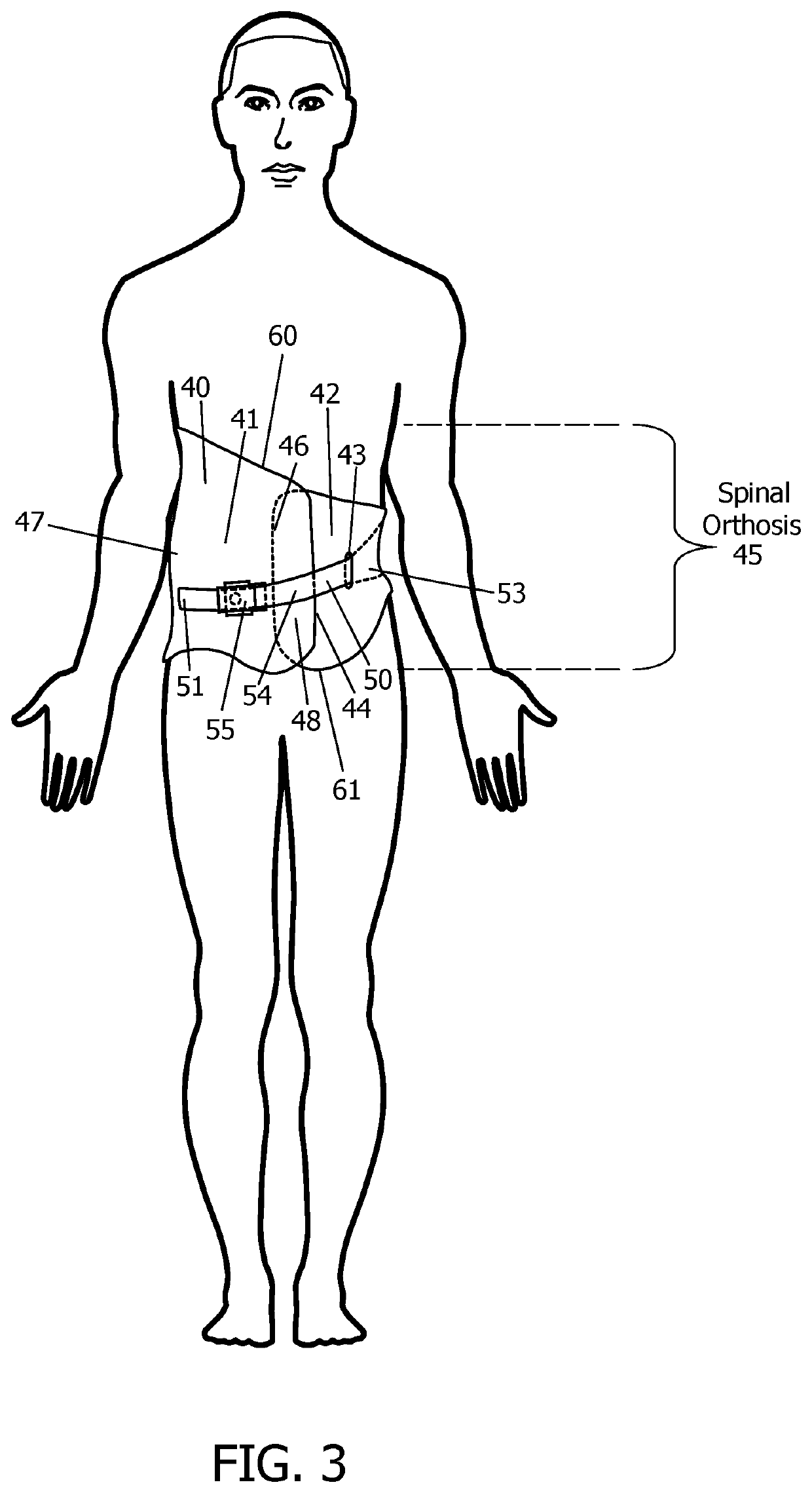
[0049]The spinal orthosis according to the present disclosure presents an advantage over prior art in harnessing the inherent properties of a low profile brace shell, specifically the property of storing elastic potential energy when bent, to create and maintain corrective dynamic tension on at least one strap. The configuration of this spinal orthosis requires only a minimal number of individual components exposed on the outer surface of a single piece brace shell to maintain dynamic corrective forces on the wearer's torso. The dynamic corrective forces are maintained during changes in body position, torso dimensions, and across a range of movement enabling the device to apply corrective forces on the body after a degree of correction has previously been achieved without the need for adjustment to the brace shell or hardware thereon.

[0050]The spinal orthosis presents these advantages while maintaining a minimal number of straps and, with no additional hardware purposed...


PUM


Abstract

An improved spinal orthosis for treating scoliosis comprises a semi-rigid brace shell with a split extending from a top end to a bottom end, and a cavity to receive the torso of a wearer. The brace shell defines at least one hole. At least one strap extends inside of a portion of the brace shell, through the at least one hole and around a portion of the outside of the brace shell across the split in the brace shell. The at least one strap is tensioned and the brace shell is closed around the wearer by pulling a first end of the at least one strap and detachably fastening it to the brace shell. The tensioned strap harnesses the elastic potential energy of the closed brace shell to apply dynamic corrective forces to the area of the user's torso most proximate to the apex of the spinal curvature.

Description

CROSS-REFERENCE TO RELATED APPLICATIONS[0001]This application claims the benefit of U.S. Provisional Patent Application No. 62 / 571,795, filed 2017 Oct. 13 by the present inventor, which is hereby incorporated by reference herein in its entirety.FIELD OF THE INVENTION[0002]The invention relates generally to an orthopedic device, and more specifically to a spinal orthosis for providing alignment to a spine.BACKGROUNDPrior Art[0003]The following is a tabulation of some prior art that presently appears relevant:[0004]U.S. PatentsPat. No.Kind CodeIssue DatePatentee9,398,972B22016 Jul. 26Yip et al.8,795,213B22014 Aug. 5Mills7,967,767B22011 Jun. 28Ogilvie7,766,850B22010 Aug. 3Simanovsky5,599,286A1997 Feb. 4Labelle et al.5,503,621A1996 Apr. 2Miller5,256,135A1993 Oct. 26Avihod5,012,7981991 May 7Graf et al.4,688,5581987 Aug. 25Hooper, Jr. et al.4,285,3361981 Aug. 25Oebser et al.4,245,6271981 Jan. 20Mignard4,230,1011980 Oct. 28Gold4,202,3271980 May 13Glancy3,282,2641966 Nov. 1N.C. Connelly3,09...

Claims


Application Information

Patent Timeline
Patent Type & Authority Patents(United States)
IPC IPC(8): A61F5/02
CPCA61F5/028A61F5/022A61F5/026
Inventor HAWKINS, MICHAEL BROWNING
Owner HAWKINS MICHAEL BROWNING
Learn More