
Display device

a display device and display technology, applied in the field of display devices, can solve the problems of difficulty in achieving a high resolution of the display device, and achieve the effect of preventing color-breakup and high resolution

Active Publication Date: 2020-10-13
SAMSUNG DISPLAY CO LTD
View PDF18 Cites 2 Cited by
  • Summary
  • Abstract
  • Description
  • Claims
  • Application Information

AI Technical Summary

Benefits of technology

The patent describes a display device that can show a high number of colors while preventing color breaks. This is achieved by using multiple light-emitting diodes in each pixel. The technical effect is better display quality with more accurate colors.

Problems solved by technology

However, when each pixel includes only one light-emitting element, an area of each pixel is relatively large, which may make it difficult to achieve a high resolution of the display device.

Method used


Image

  • Display device
  • Display device
  • Display device

Examples


first embodiment

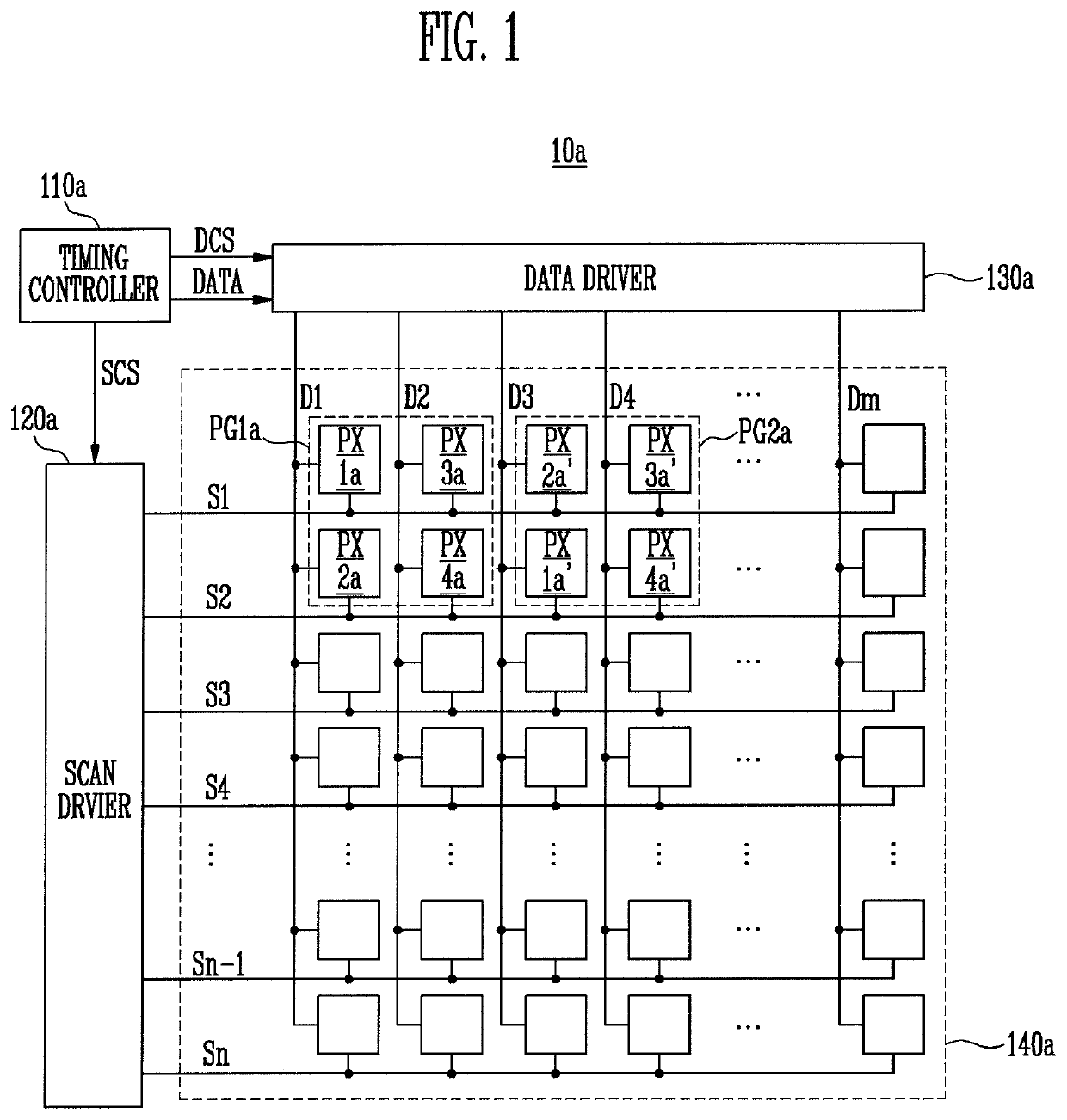
[0052]FIG. 1 is a diagram illustrating a display device 10a according to the present disclosure.

[0053]Referring to FIG. 1, a display device 10a according to the first embodiment of the present disclosure includes a timing controller 110a, a scan driver 120a, a data driver 130a, and a display unit 140a.

[0054]The timing controller 110a receives an image signal and an image control signal from a host system, such as an external application processor (AP). For example, the image signal may include a red image signal, a green image signal, a blue image signal, and the like. For example, the image control signal may include a data enable signal, a vertical synchronization signal, a horizontal synchronization signal, and the like. The data enable signal may be an indicator indicating whether the image signal is transmitted or not. The vertical synchronization signal may be an indicator indicating the start or end of the image frame constituting each viewpoint of a moving picture. The hori...

second embodiment

[0133]FIG. 11 is a diagram illustrating a display device according to the present disclosure.

[0134]Referring to FIG. 11, a display device 10b according to the second embodiment of the present disclosure includes a timing controller 110b, a scan driver 120b, a data driver 130b, a display unit 140b, an emission controller 150b, and a power supplier 160b.

[0135]Comparing the display device 10b of the second embodiment of FIG. 11 with the display device 10a of the first embodiment of FIG. 1, the display device 10b further includes the emission controller 150b and the power supplier 160b. Hereinafter, the repeated description related to FIG. 1 will be omitted, and differences between the display devices of the first and second embodiments will be mainly described.

[0136]The timing controller 110b further generates an emission control signal ECS and a power control signal PCS. The emission control signal ECS is transmitted to the emission controller 150b, and the power control signal PCS i...


PUM

PropertyMeasurementUnit
voltagesaaaaaaaaaa
coloraaaaaaaaaa
polarityaaaaaaaaaa

Abstract

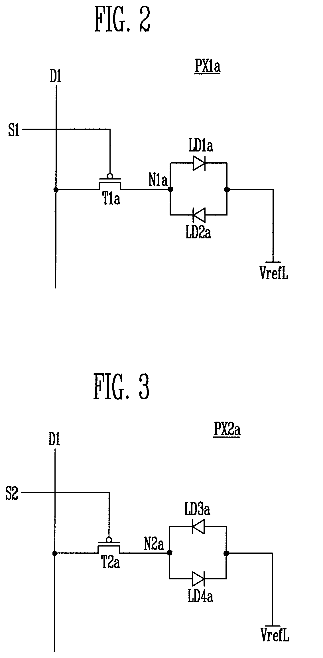
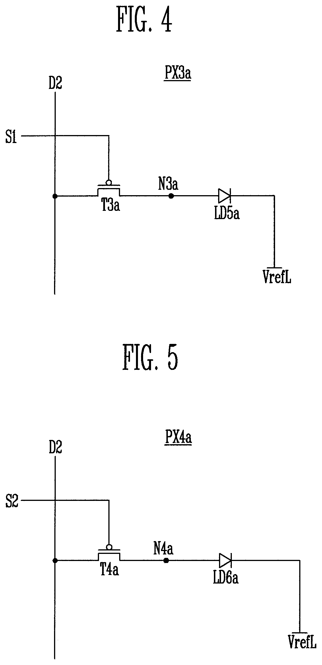
A display device includes a plurality of data lines to supply data voltages, a plurality of scan lines to supply scan signals, and a first pixel connected to at least one of the plurality of data lines, and connected to at least one of the plurality of scan lines, the first pixel including a first light-emitting diode of a first color, in which an anode is connected to a first node and a cathode is connected to a reference voltage line, and a second light-emitting diode of a second color that is different from the first color, in which an anode is connected to the reference voltage line, and a cathode is connected to the first node.

Description

CROSS-REFERENCE TO RELATED APPLICATION[0001]This application claims priority to, and the benefit of, Korean patent application 10-2018-0015620 filed on Feb. 8, 2018 in the Korean Intellectual Property Office, the entire disclosure of which is incorporated herein by reference.BACKGROUND1. Field[0002]An aspect of the present disclosure relates to a display device.2. Description of Related Art[0003]With the development of information technologies, the importance of a display device that is a connection medium between a user and information increases. Accordingly, display devices such as a liquid crystal display device, an organic light emitting display device, and a plasma display device are increasingly used.[0004]The display device displays an image by emitting light from light-emitting elements of pixels. However, when each pixel includes only one light-emitting element, an area of each pixel is relatively large, which may make it difficult to achieve a high resolution of the displa...

Claims


Application Information

Patent Timeline
Patent Type & Authority Patents(United States)
IPC IPC(8): G09G3/3208G09G3/32
CPCG09G3/32G09G3/3208G09G2300/0452G09G2300/0809G09G2320/0242G09G2300/0823G09G3/3291G09G3/3266G09G2310/0256G09G2300/0465G09G2300/08G09G2300/0842G09G2300/0861G09G2300/0804G09G3/2003
Inventor CHO, HYUN MINKIM, SUNG CHULCHU, HYE YONGKANG, JONG HYUKKIMSONG, KEUN KYUIM, HYUN DEOK
Owner SAMSUNG DISPLAY CO LTD
Learn More