Micromechanical component, micromirror-based laser system, and method for monitoring a micromirror-based laser system comprising dual sensor diodes for sensing temperature and light intensity

a laser system and micromechanical technology, applied in the field of micromechanical components, can solve the problems of preventing the operation of the laser source, affecting presenting a significant hazard potential, so as to achieve the effect of preventing the operation of the laser system, reducing the risk of damage, and improving the quality of the laser system

Active Publication Date: 2020-10-06
ROBERT BOSCH GMBH
View PDF12 Cites 2 Cited by
  • Summary
  • Abstract
  • Description
  • Claims
  • Application Information

AI Technical Summary

Benefits of technology

[0007]In accordance with the present invention, the functionality of a laser system is verified in that two sensor diodes are situated on a shared carrier substrate in a micromechanical component of such a laser system. One of the two sensor diodes is designed as a photodiode and provides an output signal which corresponds to an incidence of light. A possible incidence of light in the micromechanical component may thus be detected by this photodiode. To compensate for possible interfering effects, the output signal of the photodiode is compared to an output signal of a further sensor diode. The further sensor diode is independent of an incidence of light inside the micromechanical component and supplies an output signal corresponding to a temperature. In this way, possible temperature influences on the photodiode may be compensated for. Since the photodiode and the further diode for temperature monitoring are situated on a shared carrier substrate, a particularly simple and cost-effective construction may be implemented.
[0009]In this way, reliable and simultaneously very efficient monitoring of the scattered light in the micromechanical component may be achieved. If no scattered light may be detected by the photodiode in the micromechanical component, a malfunction of the laser system may thus be inferred therefrom. In such a case, the further operation of the laser system may be entirely or partially prevented for safety reasons.
[0011]According to another specific embodiment of the present invention, the micromechanical component includes a reflector. The reflector is designed to deflect light in the micromechanical component. In particular, the reflector may deflect the light in the micromechanical component in the direction of the second sensor diode. In this way, the light concentration may be increased at the second sensor diode, i.e., the photodiode. The photodiode may thus supply a stronger output signal.

Problems solved by technology

They may represent a significant hazard potential.
If proper operation of a laser system is not possible, the operation of the laser source thus has to be prevented.
In such a case, the further operation of the laser system may be entirely or partially prevented for safety reasons.

Method used


Image

  • Micromechanical component, micromirror-based laser system, and method for monitoring a micromirror-based laser system comprising dual sensor diodes for sensing temperature and light intensity
  • Micromechanical component, micromirror-based laser system, and method for monitoring a micromirror-based laser system comprising dual sensor diodes for sensing temperature and light intensity
  • Micromechanical component, micromirror-based laser system, and method for monitoring a micromirror-based laser system comprising dual sensor diodes for sensing temperature and light intensity

Examples


Embodiment Construction

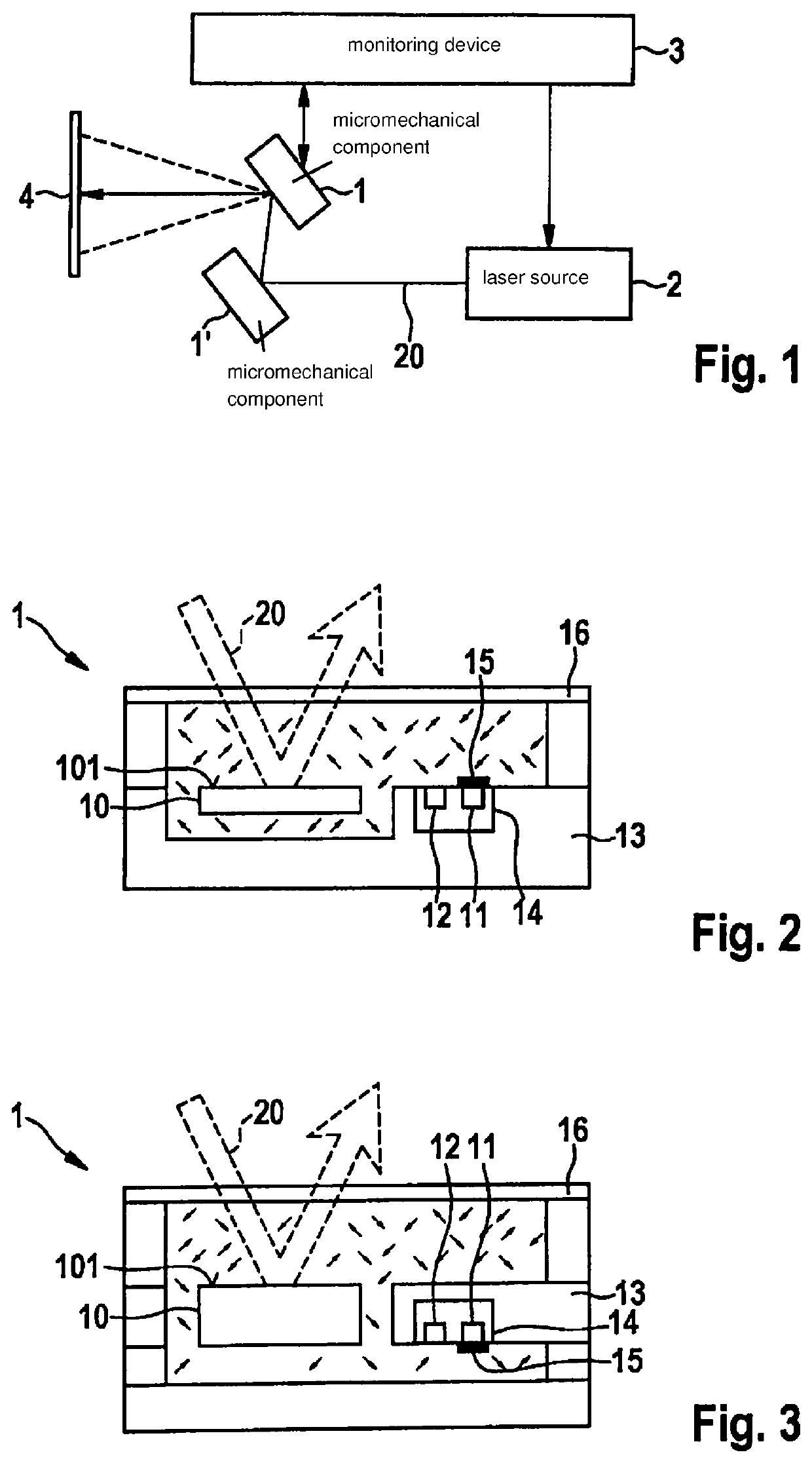
[0024]FIG. 1 shows a schematic representation of a micromirror-based laser system according to one specific embodiment. A laser source 2 emits a laser beam 20. Laser beam 20 may thereupon be deflected by one or multiple micromechanical components 1 and 1′. Micromechanical components 1 and 1′ deflect the laser beam in such a way that a predefined pattern is depicted, for example, on a phosphor screen 4. Phosphor screen 4 may additionally also be used, for example, for converting the wavelength of the laser light into light of another wavelength. The control of the micromechanical components may be carried out, for example, via suitable control electronics. In particular, these control electronics may also include a monitoring device 3, which checks the proper status of the laser system and deactivates laser source 2 in the event of the detection of a malfunction. For this purpose, monitoring device 3 may detect scattered light occurring in micromechanical component 1, for example. As...


PUM

PropertyMeasurementUnit
temperatureaaaaaaaaaa
light intensityaaaaaaaaaa
poweraaaaaaaaaa

Abstract

A micromechanical component for a micromirror-based laser system for detecting an incident laser beam. Two sensor diodes are situated on a shared substrate in the micromechanical component, only one of the two sensor diodes being designed as a photodiode. The further sensor diode supplies an output signal independent of an incidence of light. By comparing the two output signals of the two diodes, an incidence of light in the micromechanical component may be inferred.

Description

FIELD[0001]The present invention relates to a micromechanical component, and also a micromirror-based laser system including a micromechanical component. Furthermore, the present invention relates to a method for monitoring a micromirror-based laser system.BACKGROUND INFORMATION[0002]German Patent Application No. DE 10 2013 222 585 A1 describes a micro-projector including a laser light source and a movable micromirror for deflecting a laser beam. The micro-projector includes a laser light source, a laser being able to be operated in pulsed operation at a power which is greater than the greatest possible power in continuous operation.[0003]Laser systems including micromirrors are employed in numerous fields of use. A laser is guided onto a movable micromechanical mirror. This mirror represents, together with its controller, a microelectromechanical system (MEMS). Inter alia, laser sources having high power classes are also used for such laser systems. They may represent a significant...

Claims


Application Information

Patent Timeline
Patent Type & Authority Patents(United States)
IPC IPC(8): G01J1/44G02B26/08G01J1/42
CPCG02B26/0833G01J1/44G01J1/4228G01J2001/4242G01J2001/446H04N9/3129H04N9/3194G02B26/105
Inventor ROCZNIK, MARKO
Owner ROBERT BOSCH GMBH
Why Eureka
Try Eureka