Bearing cage, rolling element bearing and method

a technology of bearings and cages, applied in the direction of bearing components, shafts and bearings, mechanical equipment, etc., can solve the problems of unfavorable bearing performance, sharp edges and corners, etc., and achieve the effect of reliable and stable operation, easy manufacturing and convenient operation

Active Publication Date: 2020-09-08
AB SKF
View PDF17 Cites 0 Cited by
  • Summary
  • Abstract
  • Description
  • Claims
  • Application Information

AI Technical Summary

Benefits of technology

The present patent aims to provide a bearing cage for a rolling bearing that is easy to manufacture, flexible, and reliable. The design offers a folded portion in the cage pocket, which allows for the use of thinner sheet metal elements and reduces weight and material cost. The folded portion also creates a functional cage that can use thin sheets as raw material, which is not bearing size specific. The contact portion between the cage and the rolling element is emanating from a smooth side surface of the sheet metal element, which improves tribology compared to cut surfaces in known cage designs. Another technical feature is the undulating wave-like profile of the second circumferentially extending element, which improves the cage strength and makes it more robust and rigid. The bearing cage may also have additional portions, such as an additional guiding surface, a lubrication reservoir, or to increase rigidity. These portions may also have a fold that extends in an axial, radial, or circumferential direction of the bearing cage.

Problems solved by technology

Such surfaces may present sharp edges and corners which would not be favorable for the bearing's performance.

Method used


Image

  • Bearing cage, rolling element bearing and method
  • Bearing cage, rolling element bearing and method
  • Bearing cage, rolling element bearing and method

Examples


Embodiment Construction

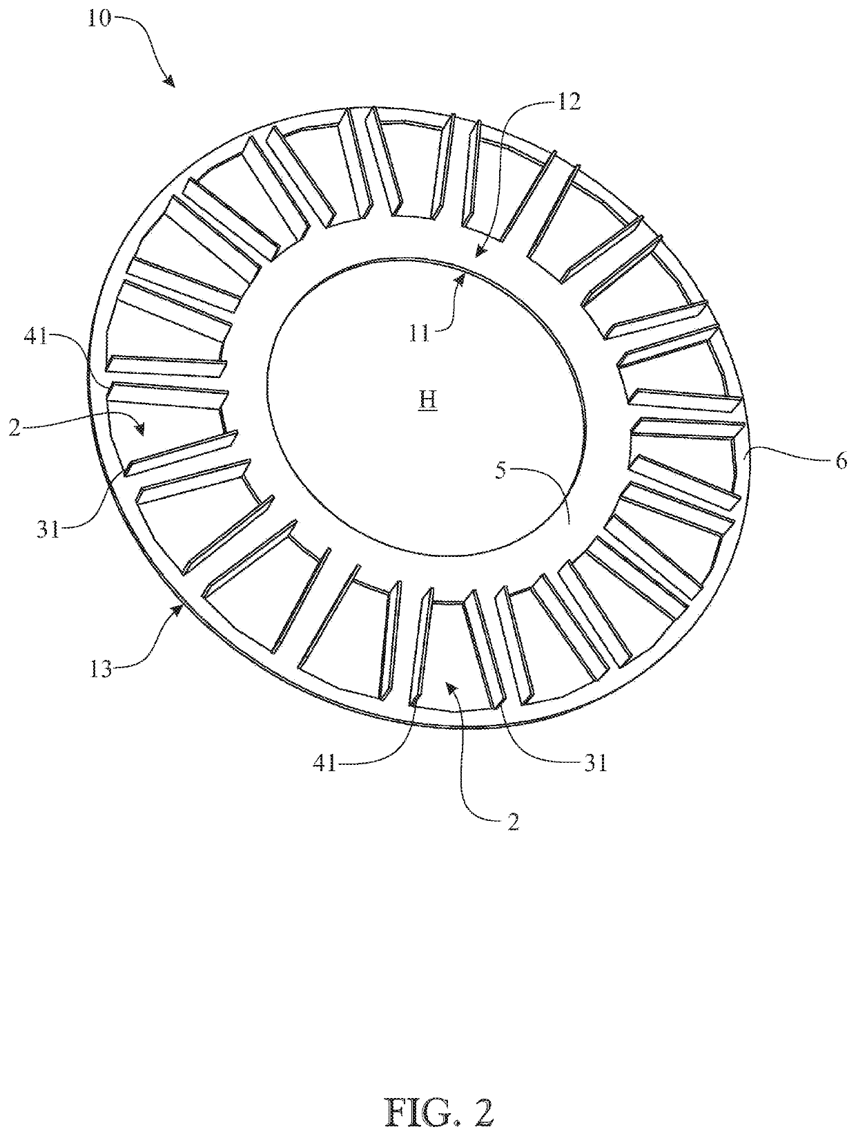
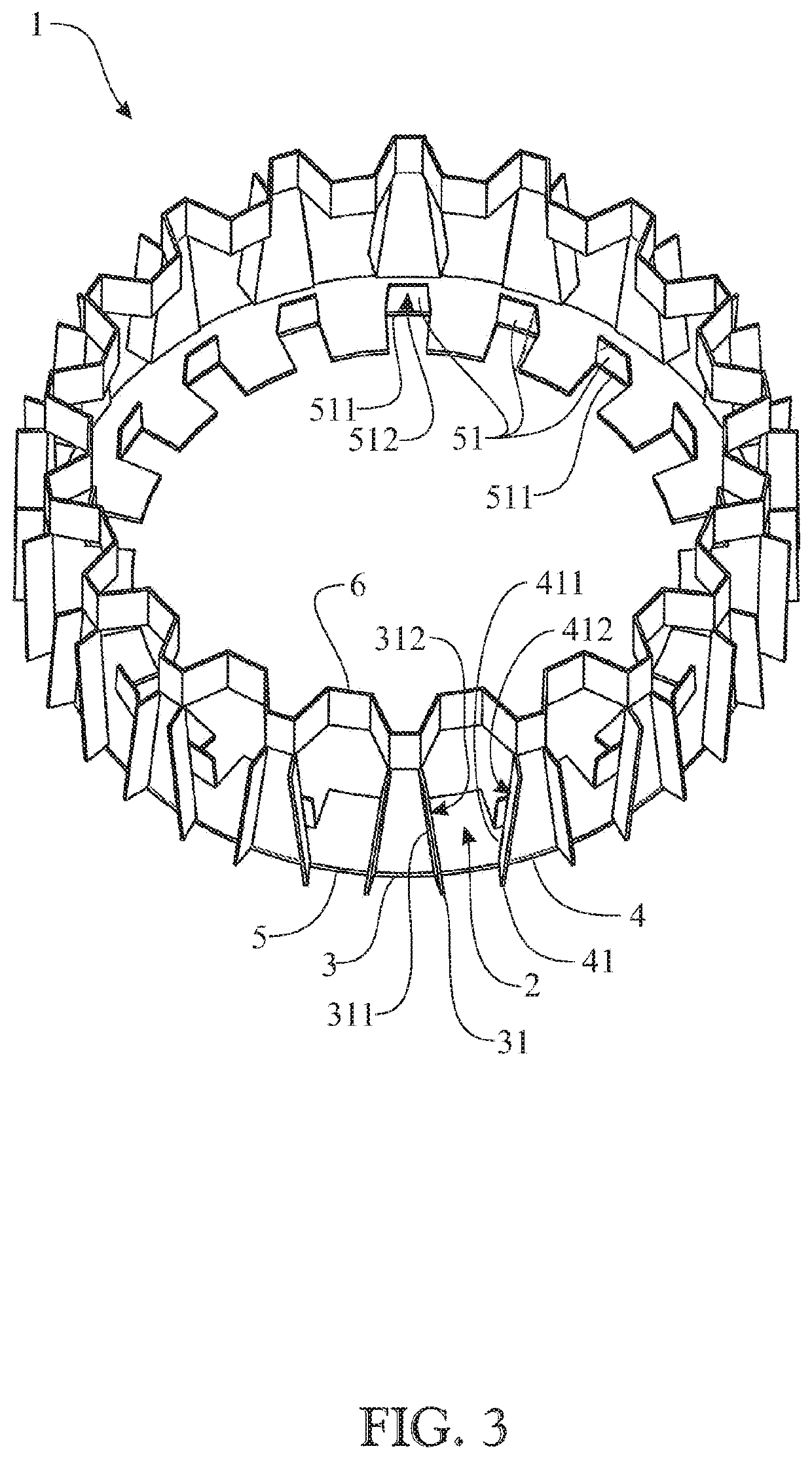
[0048]FIG. 1 illustrates a bearing cage 1 according to an embodiment of the present disclosure. The bearing cage 1 is designed for retaining rolling elements of a rolling element bearing (not shown in this figure), wherein the bearing cage 1 is made of a sheet metal element. The bearing cage 1 comprises at least one cage pocket 2 meant to receive at least one rolling element when the bearing cage 1 is in use, wherein the at least one cage pocket 2 is formed by two adjacent cage bars 3 and 4 which extend axially between a first and a second axially displaced ring element 5 and 6. In addition, one of the cage bars 3 presents a first portion 31, whereby the first portion 31 has been made by folding a part of the sheet metal element such that the first portion 31 extends in a radial direction of the cage 1 and such that an axially extending fold 311 is present on the cage bar. Furthermore, the radially extending first portion 31 presents at least one surface 312 which is arranged to con...


PUM


Abstract

A bearing cage for retaining rolling elements of a rolling element bearing, the bearing cage constructed from a sheet metal element. The cage having at least one cage pocket configured to receive at least one rolling element. The at least one cage pocket is formed by two abutting cage bars that extend axially between a first and a second axially displaced ring element. At least one of the cage bars includes a first portion. The first portion is constructed by folding a part of the sheet metal element such that the first portion extends in a radial direction of the cage and such that an axially extending fold is provided on the cage bar. A rolling element bearing and a method of producing the bearing cage is also provided.

Description

CROSS-REFERENCE TO RELATED APPLICATIONS[0001]This application claims priority to German patent application no. 102016224792.1 filed on Dec. 13, 2016, the contents of which are fully incorporated herein by reference.BACKGROUND OF THE INVENTION[0002]Technical Field of the Present Invention According to a first aspect, the present disclosure regards a bearing cage for retaining rolling elements of a rolling element bearing.[0003]According to a second aspect, the present disclosure regards a rolling element bearing comprising a bearing cage according to the first aspect of the present disclosure.[0004]According to a third aspect, the present disclosure regards a method for producing a bearing cage according to the first aspect of the present disclosure.DESCRIPTION OF RELATED ART[0005]It is well known to make use of cages or retainers in a rolling element bearing for retaining the rolling elements in the bearing. There are different types of cage designs available, as well as different c...

Claims


Application Information

Patent Timeline
Patent Type & Authority Patents(United States)
IPC IPC(8): F16C33/54F16C33/38F16C19/36
CPCF16C33/543F16C33/3806F16C19/36B21D53/12F16C33/541F16C33/56F16N2210/14F16C19/38F16C33/545
Inventor KULLIN, ARNE LARS JONAS
Owner AB SKF
Why Eureka
Try Eureka