
Formwork device

Active Publication Date: 2020-09-01
UMDASCH GRP NEWCON GMBH
View PDF71 Cites 1 Cited by
  • Summary
  • Abstract
  • Description
  • Claims
  • Application Information

AI Technical Summary

Benefits of technology

The present invention relates to a formwork device for a battery formwork used in the production of structural elements, particularly prefabricated concrete elements. The device comprises at least two partition walls with formwork elements attached, and a formwork panel that can be folded and transferred between the walls. The formwork panel has a formwork front side and a formwork rear side. The formwork front side can be magnetic, and the formwork panel can also have rollers for easy positioning and movement. The device simplifies the production process and allows for flexibility in the production process.

Problems solved by technology

On the other hand, handling the large and relatively heavy partition walls is not very easy.
Also, fitting the partition walls with formwork elements is quite laborious.
Complicated geometries can also be realized therewith, which are difficult to realize with conventional formwork elements.

Method used


Image

  • Formwork device
  • Formwork device
  • Formwork device

Examples


Embodiment Construction

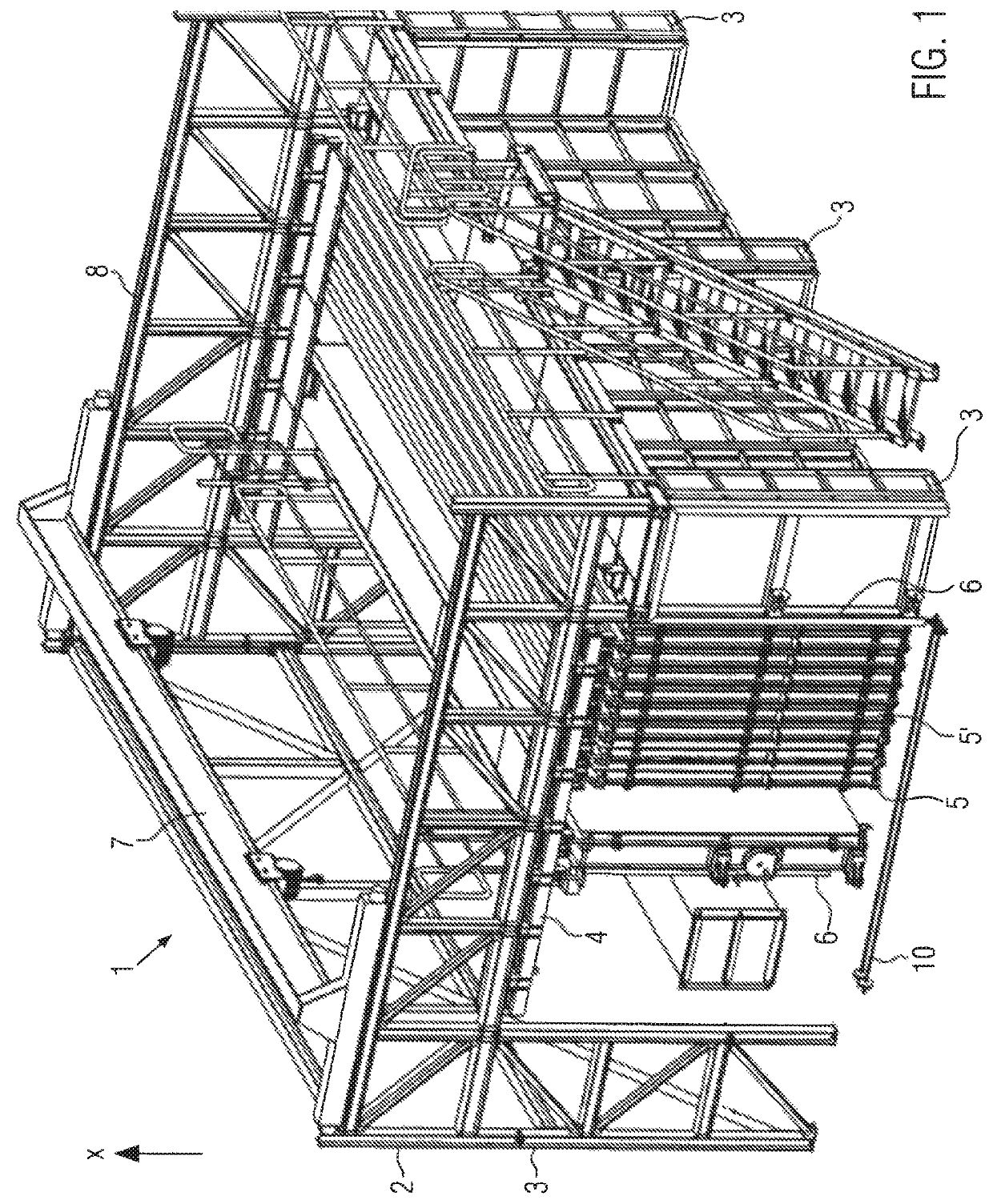
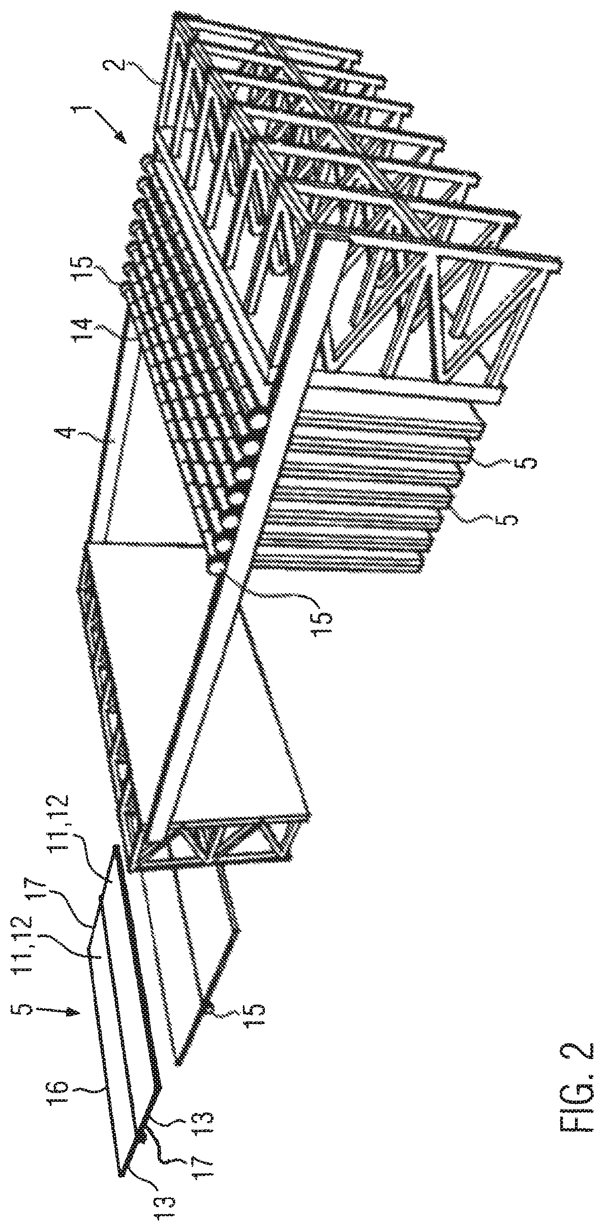
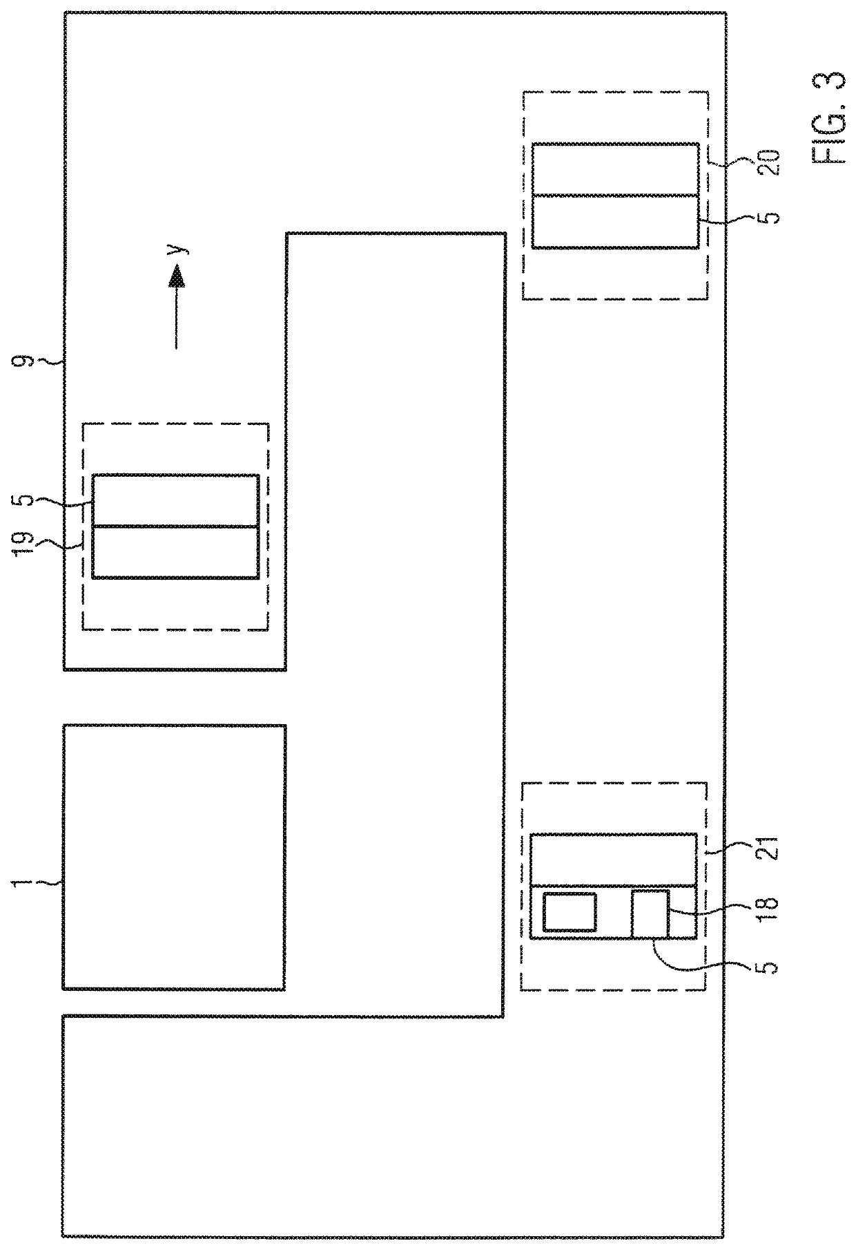
[0030]FIG. 1 shows a schematic representation of a battery formwork 1 with formwork devices 5. Battery formwork 1 is used for the production of structural elements, not shown, and in particular of prefabricated concrete elements for buildings. Battery formwork 1 comprises a support frame 2 with bearing sections 3 spaced from each other. The number of bearing sections 3 in FIG. 1 is only by way of example and can be adapted to the circumstances. Furthermore, battery formwork 1 comprises two support devices 4 in which partition walls 5′ (bulkhead walls) and formwork devices 5 are received in a suspended and movable manner, i.e. in the present embodiment, in a slidable manner Formwork devices 5 are there located between the partition walls 5′. A cavity to be filled with concrete is formed between at least one partition wall 5′ and one formwork device 5, where formwork device 5 preferably supports formwork elements 18 which define the contour of the prefabricated concrete element. Formw...


PUM

PropertyMeasurementUnit
Magnetismaaaaaaaaaa

Abstract

The present invention relates to a formwork device for a battery formwork for the production of structural elements, in particular prefabricated concrete elements, which comprises at least two partition walls and the formwork device comprises two formwork panels that are connected to one another, preferably in an articulated manner, in order to be transferred from an unfolded state to a folded state, where each formwork panel comprises a formwork front side for attaching formwork elements and a formwork rear side, and the formwork rear sides of the two formwork panels face each other in the folded state and the formwork device is intended to be positioned in the folded state between the partition wall. The present invention further relates to an arrangement consisting of a battery formwork and at least one formwork device according to the invention, where the formwork device is arranged suspended in the battery formwork.

Description

CROSS-REFERENCE TO RELATED APPLICATIONS[0001]The present application is a U.S. National Phase of International Patent Application Serial No. PCT / EP2016 / 061220, entitled “FORMWORK DEVICE” filed on May 19, 2016. International Patent Application Serial No. PCT / EP2016 / 061220 claims priority to German Patent Application No. 10 2015 209 157.0, filed on May 19, 2015. The entire contents of each of the above-cited applications are hereby incorporated by reference in their entirety for all purposes.TECHNICAL FIELD[0002]The present invention relates to a formwork device for a battery formwork for the manufacture of structural elements, in particular prefabricated concrete elements, which comprises at least two partition walls.BACKGROUND AND SUMMARY[0003]Battery formworks are often used in the series production of prefabricated concrete elements. Prefabricated concrete elements are often used, in particular, for building houses with precast concrete slabs. These prefabricated concrete elements...

Claims


Application Information

Patent Timeline
IPC IPC(8): E04G9/08E04G11/08E04G15/02E04G19/00B28B7/24B28B7/08B28B7/00E04B1/04E04B7/20E04B5/04
CPCE04G9/083B28B7/002B28B7/08E04G15/02E04G19/003B28B7/245E04G11/08E04B7/20E04B1/04E04B5/04E04B2103/02B28B1/08B28B7/0002B28B7/42
Inventor SCHREYER, BERND
Owner UMDASCH GRP NEWCON GMBH
Learn More