Gas turbine having a lifting mechanism

a technology of lifting mechanism and gas turbine, which is applied in the direction of cranes, machines/engines, mechanical equipment, etc., can solve the problems of reducing affecting the maintenance work, and the insufficient access of all maintenance work, so as to reduce the need for space, the lifting mechanism is maintenance-friendly and space-saving, and the flexibility of use of the lifting mechanism can be increased.

Inactive Publication Date: 2017-11-02
SIEMENS ENERGY GLOBAL GMBH & CO KG
View PDF2 Cites 2 Cited by
  • Summary
  • Abstract
  • Description
  • Claims
  • Application Information

AI Technical Summary

Benefits of technology

The maintenance access in a gas turbine is a manhole designed to allow a person to pass through and maintain or replace components that are exposed to hot gas during operation. The manhole has a fastening section that attaches a closure element, like a cover, to safely enclose the hot gases during operation. Boom arms can be designed as telescopic arms, providing increased flexibility for maintenance work on the outer housing of the gas turbine. Ultimately, the patent text aims to provide a better maintenance access for gas turbines.

Problems solved by technology

During maintenance work on a gas turbine, it is sometimes necessary to support or lift heavy loads.
This access is not adequate for all maintenance work, however, and for this reason in many cases cannot replace the removal of other components on the outer housing of the gas turbine in order to make the interior regions accessible.
A disadvantage of these mechanisms known from the prior art is that the lifting mechanisms to be provided are of a very complex design.
Usually, these are movement units equipped with rollers or wheels, which in addition also require a relatively large amount of space and for this reason significantly limit the space that can be made available to the maintenance personnel.
On account of the high costs for such lifting devices, it is also usually not possible for economic reasons to provide more than one lifting device.
This again hinders the procedure of the maintenance work, since, for example, it is only possible for a crane used to be available for one lifting or supporting operation, during which period, however, a second lifting or supporting device would possibly be necessary.
Furthermore, within the scope of the maintenance work, it is usually essential to leave the lifted or supported loads on the lifting device, since improper setting down of the object in question would only lead to very expensive follow-up measures.
These disadvantages give rise to the technical requirement of proposing a lifting mechanism, or a crane system comprising such a lifting mechanism, which can avoid these disadvantages.

Method used


Image

  • Gas turbine having a lifting mechanism
  • Gas turbine having a lifting mechanism
  • Gas turbine having a lifting mechanism

Examples


Embodiment Construction

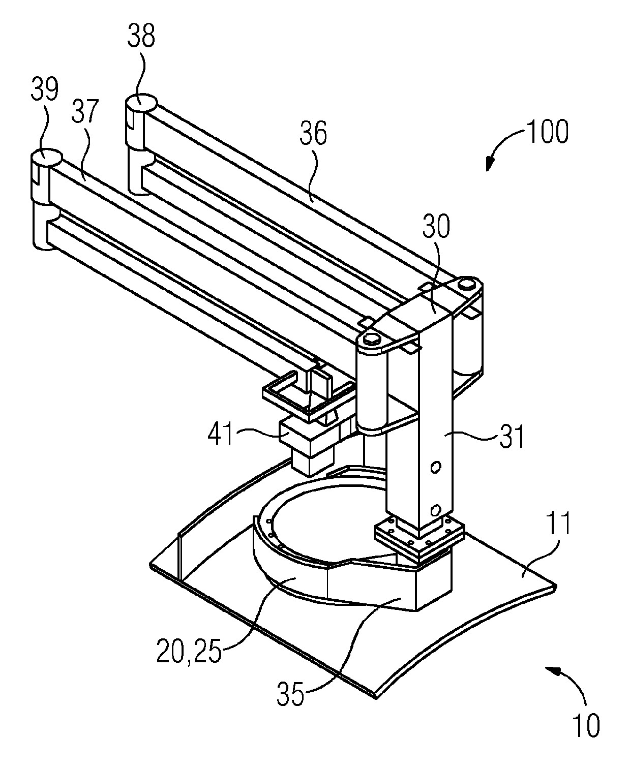
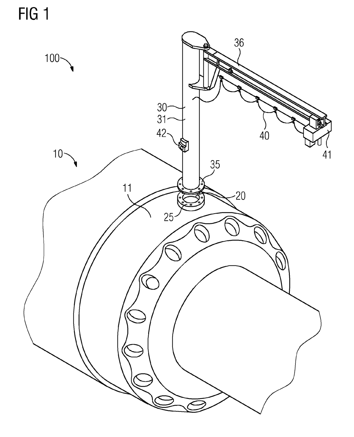
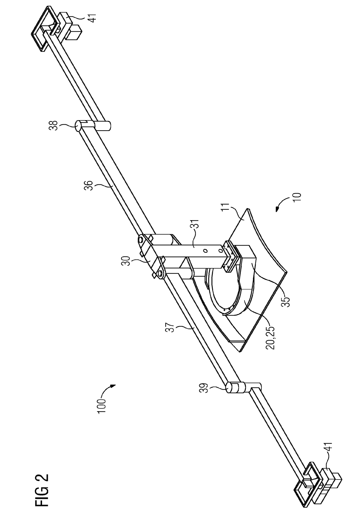
[0035]FIG. 1 shows a first embodiment of the crane system 100 according to the invention with an embodiment of the lifting mechanism 30 according to the invention, which mechanism is fitted to a fastening section 25 of a manhole 20 on the outer housing 11 of the gas turbine 10 via a mating fastening section 35. Besides the manhole 20, the outer housing 11 provides a further number of housing openings (burner openings), which are not provided with reference signs, via which the interior of the gas turbine 10 and thus the components acted upon by hot gas can be reached by the maintenance personnel.

[0036]The lifting mechanism 30 itself is designed as a pillar crane, which has a pillar 31 which has the mating fastening section 35 in question at one end, said mating fastening section being connected to the fastening section 25 of the manhole 20. The connection of the two sections 25, 35 is realized by means of a flange connection, since the fastening section 25 is designed as a fastening...


PUM


Abstract

A crane system having a gas turbine that has a manhole on the outer housing thereof, the manhole being designed to open up a maintenance access to hot gas parts of the gas turbine in the open state of the manhole, which is provided with a fastening section; the crane system further has a hoisting mechanism that includes a mating fastening section which is connected to the fastening section of the manhole in such a way that the hoisting mechanism introduces weights that same has to lift into the outer housing of the gas turbine.

Description

CROSS REFERENCE TO RELATED APPLICATIONS[0001]This application is the US National Stage of International Application No. PCT / EP2015 / 075817 filed Nov. 5, 2015, and claims the benefit thereof. The International Application claims the benefit of European Application No. EP14193683 filed Nov. 18, 2014. All of the applications are incorporated by reference herein in their entirety.FIELD OF INVENTION[0002]The present invention relates to a crane system for a gas turbine and to a lifting mechanism which can be used within the scope of such a crane system, and to a method for producing such a crane system.BACKGROUND OF INVENTION[0003]During maintenance work on a gas turbine, it is sometimes necessary to support or lift heavy loads. For example, when replacing a burner, the latter usually has to be removed as a unit out of or from the gas turbine. The loads to be lifted or supported in this case are of such a size that a specialized lifting device has to be used. In addition, numerous gas tur...

Claims


Application Information

Patent Timeline
IPC IPC(8): B66C23/18B66C23/02F01D25/28
CPCB66C23/18F01D25/285F05D2220/32B66C23/027F05D2230/80B66C23/025
Inventor GRIESE, ANDREASMULLER, DIRKTRITSCH, KATRINGELLENTHIEN, HEIKO
Owner SIEMENS ENERGY GLOBAL GMBH & CO KG
Why Eureka
Try Eureka