
Solar shingle roofing kit

a solar panel and kit technology, applied in photovoltaic energy generation, photovoltaics, electrical appliances, etc., can solve the problems of affecting the performance of solar panels, shortening the life of solar panels, and performing slightly worse than monocrystalline si solar panels

Active Publication Date: 2020-08-18
PV TECHNICAL SERVICES INC
View PDF10 Cites 3 Cited by
  • Summary
  • Abstract
  • Description
  • Claims
  • Application Information

AI Technical Summary

Benefits of technology

The solar shingle roofing kit is a collection of solar modules that can be used to create a solar roof. The solar modules have a unique frame that securely holds the solar panel in place on the roof. The frame has a ridge that fits into a clamp on the roof, and the solar panel is sealed within the frame to prevent leaks. The kit also includes interchangeable shingles that can be used instead of solar modules, and the shingles have a ridge that fits into the same clamp on the roof. The technical effects of this patent include a more efficient and durable solar roof that is easy to install and repair.

Problems solved by technology

This technically means that they perform slightly worse than monocrystalline Si solar panels in high temperatures.
Heat can affect the performance of solar panels and shorten their life spans.
However, this effect is minor.
Because of lower silicon purity, polycrystalline Si solar panels are not quite as efficient as monocrystalline Si solar panels.
Polycrystalline Si panels have a lower space-efficiency.
The panels which are produced are large, rigid and fragile.
Bolting to a roof necessitates holes being punched through shingles with the potential for water leakage.
With solar panels suspended above the roof, there is a possibility of the panels lifting during high winds.
Thin-film solar panels are in general not very useful for in most residential situations.
They require a lot of space.
Low space-efficiency also means that the costs of PV-systems (e.g. support structures and cables) will increase.
It is expected that the cost to manufacture the components taught by Allen would be quite high since they are not common mass produced articles or simple extrusions.
The splice plate in the kits taught by Allen that connects the left and right solar panels makes it be impossible to replace one failed solar panel in the array.

Method used


Image

  • Solar shingle roofing kit
  • Solar shingle roofing kit
  • Solar shingle roofing kit

Examples


Embodiment Construction

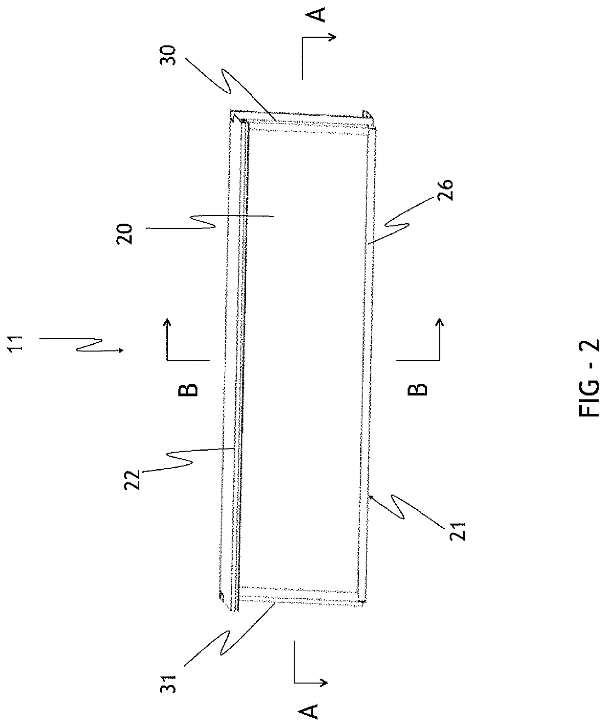
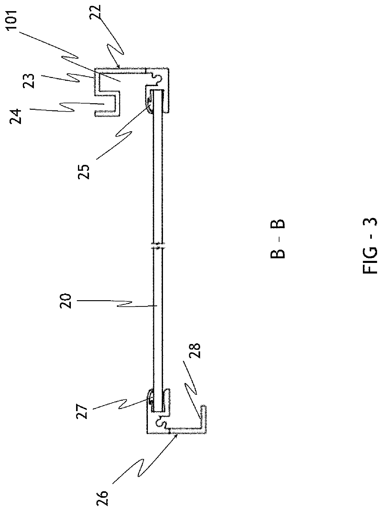
[0037]This invention is a solar shingle roofing kit for installing monocrystalline or multi-crystalline solar panel modules 11 on a roof deck to generate electricity shown generally by reference numeral 10. The solar modules 11 can be installed on a sloped roof and the modules can be cross-mixed with regular shingles 12 in a single installation. The solar modules 11 provide the functions of both covering roof and generating DC power. The shingles 12 provide only the function of covering the roof deck. The solar modules and shingles may be installed on a sloped roof to form an array, and their positions in the array can be cross-mixed. FIG. 1 illustrates showing a portion of a roof that has been covered using the solar shingle roofing kit of the present invention. As shown in FIG. 1 and FIG. 2, the solar modules 11 are generally rectangular in shape and have a fixed length and width. However, the length of shingles 12 can be equal to that of solar modules 11, and longer or shorter th...


PUM


Abstract

A solar shingle roofing kit comprises a plurality of crystalline solar panel modules, a central connector for adjoining adjacent solar modules, a starting connector to join a solar module to an eaves or a deck of a roof; left and right closures to join solar modules to the rake edges of a roof or to other kinds of commercial shingles or roof tiles, and a plurality of clamps to fasten the forgoing elements to the deck of a roof. The solar shingle roofing kit allows solar modules to be installed interchangeably with metal roof shingles. The solar shingle roofing kit allows an individual solar module to be removed and replaced without removing neighbouring modules or shingles in the event that a solar module fails.

Description

[0001]This application claims the benefit of U.S. Provisional Patent Application No. 62 / 345,223, filed May 3, 2016, which is incorporated by reference herein in its entirety.TECHNICAL FIELD[0002]The present disclosure relates the installation of solar panel modules on sloped roofs.BACKGROUND ART[0003]There are three main types of commercialized solar panels: monocrystalline silicon (Si), polycrystalline silicon (Si) and thin film. The two formers are crystalline solar panels. Monocrystalline Si solar panels have the highest efficiency rates since they are made out of the highest-grade silicon. The efficiency rates of monocrystalline Si solar panels are typically 16-22%. Monocrystalline Si solar panels are space-efficient. Since these solar panels yield the highest power outputs, they also require the least amount of space compared to any other types. Monocrystalline Si solar panels produce up to two times the amount of electricity as thin-film solar panels. Monocrystalline Si solar ...

Claims


Application Information

Patent Timeline
Patent Type & Authority Patents(United States)
IPC IPC(8): H02S20/25H02S30/10
CPCH02S20/25H02S30/10Y02B10/10Y02E10/50
Inventor GUO, LI HUI
Owner PV TECHNICAL SERVICES INC
Learn More