Eureka AIR delivers breakthrough ideas for toughest innovation challenges, trusted by R&D personnel around the world.

Framing system for solar panels

A solar panel and frame system technology, applied in the field of frame systems, can solve the problems of lack of smooth outer surface, inconsistent spacing of slats, weakened market competitiveness, etc.

Inactive Publication Date: 2003-07-02
彼得 S 厄林
View PDF0 Cites 40 Cited by
  • Summary
  • Abstract
  • Description
  • Claims
  • Application Information

AI Technical Summary

Problems solved by technology

However, known frames have fixed dimensions and therefore do not require mounting structures and do not conform to standard batten spacing such as
The fixed size also severely limits the number of commercially available PV panels that can be integrated into the frame
And custom-sized PV panels will have additional costs, which makes any system using custom-sized PV panels less competitive in the market
[0004] Other known roof-integrated framing systems require additional structure under the PV panels to ensure a weatherproof seal, or use elongated frame sections that require additional elements to attach to the roof structure, and in some cases lack smoothness both visually and externally. The outer surface

Method used


Image

  • Framing system for solar panels
  • Framing system for solar panels
  • Framing system for solar panels

Examples


Embodiment Construction

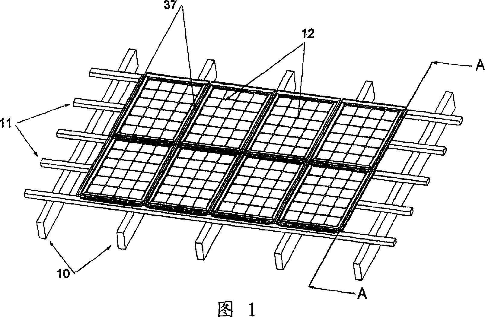
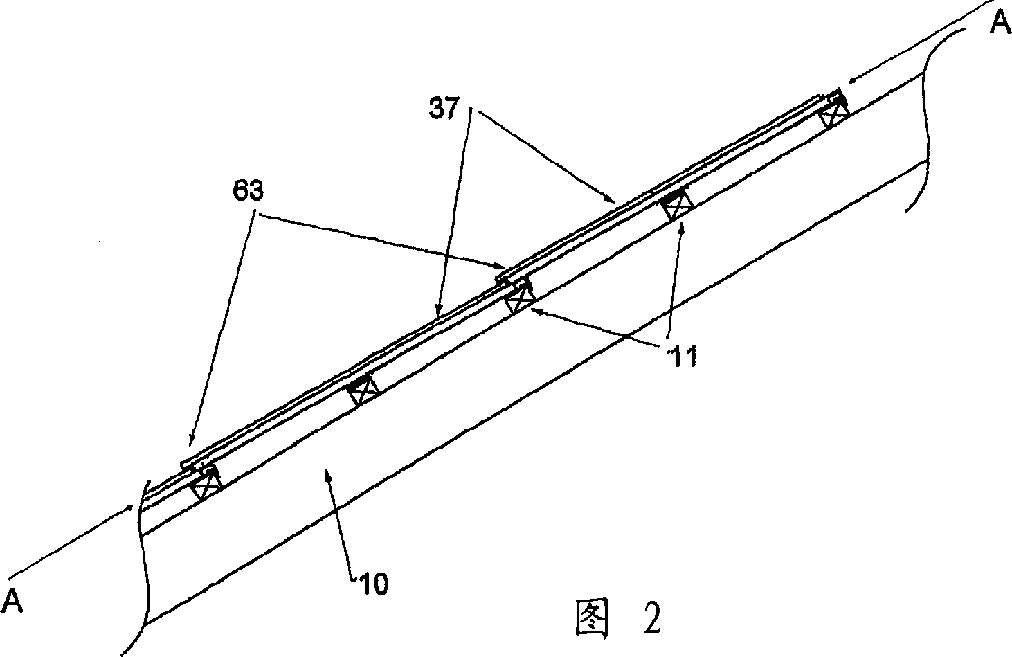
[0042] Referring first to Figures 1 to 3, the roof structure comprises: parallel and spaced apart rafters 10 with horizontal slats 11 of rectangular cross section spaced about half the length of the solar tiles. FIG. 1 shows a matrix of solar tiles 12 which are all identical and connected by gland elements 37 in weathertight relationship.

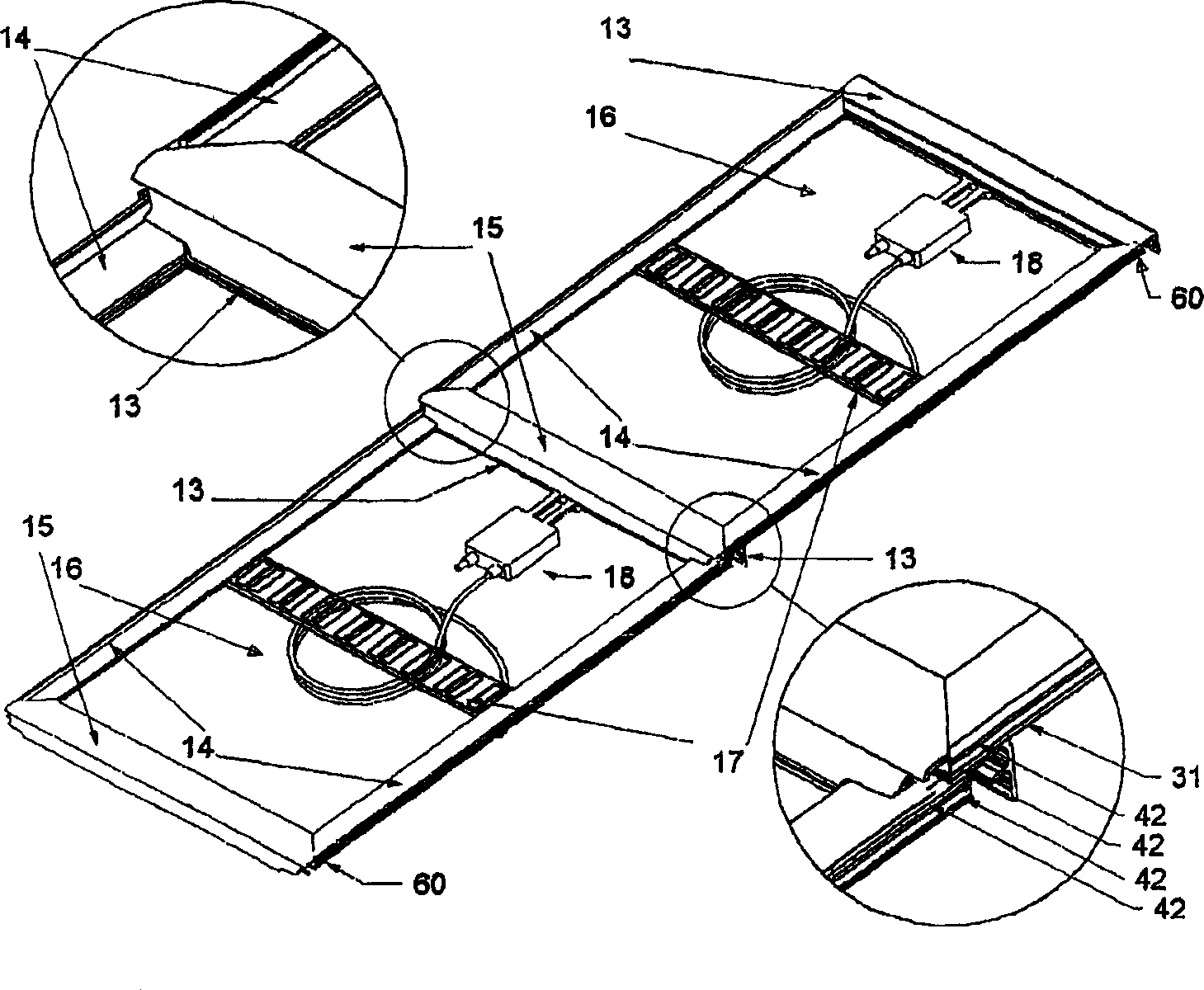
[0043] refer to image 3, there are two solar tiles seen from above, each solar tile has an upper frame member 13, a side frame member 14 and a lower frame member 15, and they are firmly sealed in a weatherproof manner by the inherent plates 16 (not shown) of the solar tile Connection and clamping. At approximately the midpoint there is provided a transverse support 17 , fixed at each end to the side frame members 14 . There may be more than one such transverse beam in a larger solar tile, in a typical example two transverse beams. image 3 Also shown is an electrical junction box 18 which is electrically connected to the solar tiles and i...


PUM


Abstract

The invention relates generally to framing systems and more particularly is concerned with systems adapted to mount panels or laminates in an array (12) on a supporting roof structure (10) of a building exemplified with the mounting of solar electric photovoltaic (PV) panels. The framing system described uses extruded elongate elements with a sealing element (37) to frame the PV panel as a weatherproof PV solar roof tile. Individual frame element profiles effectively embody the PV building integration (BiPV), or mounting method, of the solar tile within the frame itself. Only a few additional flashing components are needed to complete the PV tile array as part of the roof, or with minor variations, as a PV wall cladding. Full BiPV panel mounting methods show potential to be used for co-generation (PV / T) of solar thermal energy capture in buildings. The batten support structures (11) of the solar tile permit variation in roof batten spacing to be tolerated in retro-fit situations, make trafficable roof with the tiles possible and provide long term weather-ability as a building element through moisture reduction by air flow and smaller surface contact. Draining of internal roof condensate from the back of the tiles to the exterior is another feature of the frame system described.

Description

technical field [0001] The present invention relates generally to frame systems and in particular to systems suitable for mounting panel elements or thin-plate elements in a matrix on a support structure. The invention will be illustrated with a particular application in the field of mounting solar panels, also known as photovoltaic (PV) panels, suitable for proper installation at an angle to the horizontal and relative to the sun. However, the invention and the frame system are not limited to these applications, but extend to similar applications. In this discussion we refer to the use of the system as primarily a roof-mounted or roof-integrated application. However, with minor adjustments, the system is also suitable for use in vertical installations as an external PV sidewall cladding system. Background technique [0002] In the field of solar PV panels, proposals have been made to form them with the usual features of roof tiles, so that the PV panels can be integrated ...

Claims


Application Information

Patent Timeline
Patent Type & Authority Applications(China)
IPC IPC(8): E04D3/08E04D3/14E04D3/366E04D3/40F24J2/00F24J2/04H02S20/23
CPCF24J2002/0061Y02B10/20F24J2/045Y02E10/52Y02E10/44F24J2/5211E04D3/366E04D3/14H01L31/0482F24J2002/4665F24J2/465Y02E10/47Y02B10/12E04D2003/0818H02S20/23Y02P80/15F24S80/70F24S20/67F24S25/20F24S2020/13F24S2025/6004Y02E10/50Y02A30/60Y02B10/10
Inventor 彼得·S·厄林
Owner 彼得 S 厄林
Why Eureka
Eureka Blog
Learn More