
Firearm suppression device

a technology for suppressing devices and firearms, applied in the direction of weapons, weapon components, etc., can solve the problems of suppressor cooling, michal failing to address problems, and excessive temperature retained by the suppressor

Active Publication Date: 2020-08-18
ASCENDANCE INT LLC
View PDF43 Cites 7 Cited by
  • Summary
  • Abstract
  • Description
  • Claims
  • Application Information

AI Technical Summary

Benefits of technology

[0017]Some existing suppressor devices attempt to mitigate the high temperature issue as related to the operation of a firearm in conjunction with a suppressor device attached to the muzzle-end as used by U.S. Pat. No. 9,140,511 to Michal, et al. (Michal), herein incorporated by reference in its entirety. Michal describes a sleeve designed to interface with the outer surface of a suppressor with interior splines, and exterior splines disposed at an angle to the interior splines. The configuration of Michal provides insulation to limit heat conduction and limiting the exterior touch temperature of the sleeve when used with a suppressor. Michal fails to address problems associated with blowback. Furthermore, Michal's insulation strategy prevents the cooling of the suppressor. This leaves the firearm subjected to negative operational effects of excessive heat retained by the firearm and suppressor device.
[0031]Because the use of a suppressor is known to affect the point of impact, it is common practice to re-zero or recalibrate any optics or to simply compensate with aim to achieve a similar point of impact. It will be appreciated that it is advantageous to be able to attach or remove a suppressor from / to a firearm without affecting the point of impact. It is an aspect of the present invention to allow the rapid attachment and removal of a suppressor to / from a firearm while impacting the point of impact by less than one minute of angle.

Problems solved by technology

Where Dueck fails to address certain problems associated with the suppression of firearms is the issue surrounding blowback and excessive temperature retained by the suppressor.
Michal fails to address problems associated with blowback.
Furthermore, Michal's insulation strategy prevents the cooling of the suppressor.
This leaves the firearm subjected to negative operational effects of excessive heat retained by the firearm and suppressor device.

Method used


Image

  • Firearm suppression device
  • Firearm suppression device
  • Firearm suppression device

Examples


Embodiment Construction

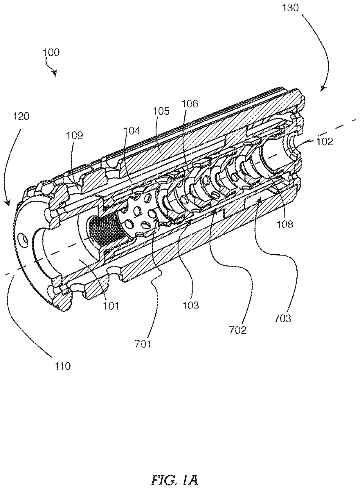
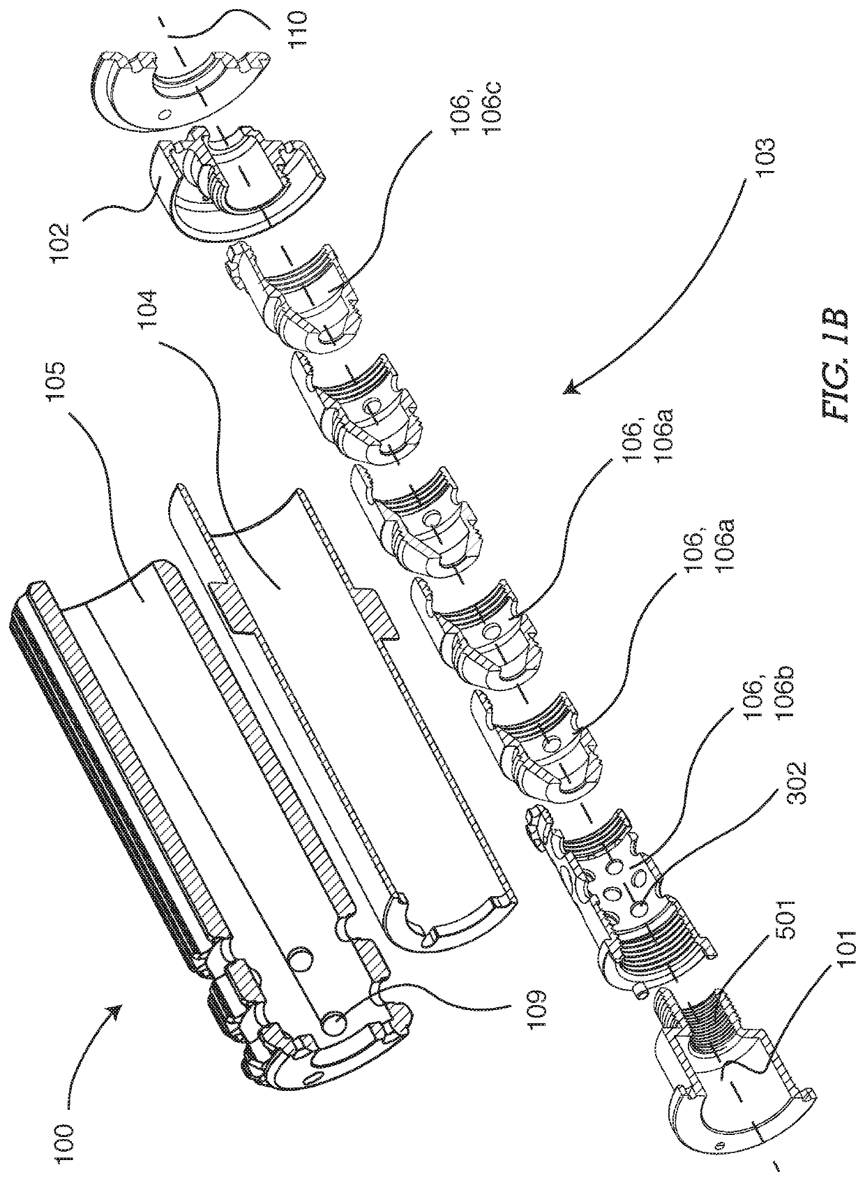
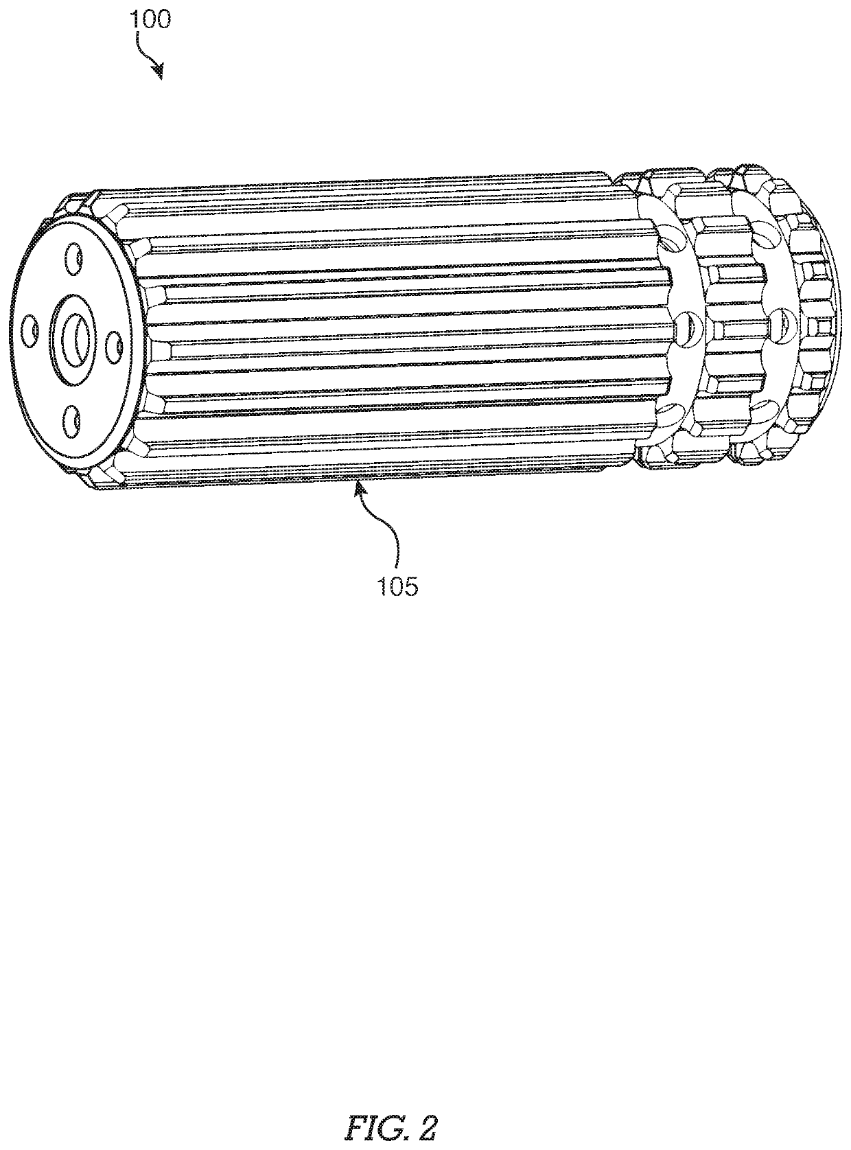
[0064]Certain embodiments of the present invention surrounding a suppressor 100, as shown in FIG. 1A and FIG. 1B, comprise a firearm engagement component 101 having a pathway 110 and a firearm attachment feature 501 for the fixation to a distal end of a firearm. Such a suppressor 100 has a proximal end 120 and a distal end of the suppressor 130 and further comprises a projectile exit component 102, a baffle system 103, a sleeve 104 and an outer housing 105. A projectile exit component 102 is open along a pathway 110, allowing for the passage of a projectile and gasses. Certain embodiments of a baffle system 103 comprise a plurality of interconnected baffles 106. A first baffle 106a, seen in FIG. 1B, comprises a hollow form with a cross-section increasing along the pathway 110 from a proximal end toward a distal end of the first baffle 106. A second baffle 106b, seen in FIG. 1B, comprises a constant internal diameter and constant outer diameter. The first baffle 106a and the second b...


PUM


Abstract

The present invention pertains in general to a suppressing apparatus for the suppression of audible, visible and infrared profiles in the operation of firearms and weapon systems. Embodiments of the invention include the use of a substantially cylindrical component having a helical opening for the dispersion of gasses in conjunction with channels and volumes configured to carry the gasses along the length of the suppressing apparatus toward a distal aspect and toward a proximal aspect alternatively.

Description

CROSS REFERENCE TO RELATED APPLICATIONS[0001]This application claims benefit to and is a continuation-in-part of nonprovisional patent application Ser. No. 16 / 106,750, Filed Aug. 21, 2018—currently pending, which is a continuation of nonprovisional patent application Ser. No. 15 / 408,224, entitled “Firearm Suppression Device”, filed on Jan. 17, 2017—now U.S. Pat. No. 10,107,581—which claims benefit of provisional patent application No. 62 / 279,801, entitled “Firearm Suppression Device”, filed Jan. 17, 2016—which all are incorporated by reference in their entirety for all purposes.FIELD OF THE INVENTION[0002]The present invention pertains in general to the suppression of firearm and weapon systems to mitigate audible, visual and temperature profiles when in use.BACKGROUND OF INVENTION[0003]Firearms, typically understood as a barreled weapon designed to launch a projectile toward an intended target have developed over centuries. Many developments have been made over the ages, but firear...

Claims


Application Information

Patent Timeline
Patent Type & Authority Patents(United States)
IPC IPC(8): F41A21/30
CPCF41A21/30
Inventor GARST, JOSEPHMCCULLUM, SEAN NATHANIEL
Owner ASCENDANCE INT LLC
Learn More