Heat utilizing device
a technology of heat utilizing device and heat dissipation device, which is applied in the direction of heat measurement, optical radiation measurement, instruments, etc., can solve the problems of limited heat dissipation from the thermistor through the atmosphere, limited heat dissipation in the support member, and limited heat dissipation in the wiring layer, so as to improve the temperature increase efficiency of the thermistor, and limit the effect of radiation hea
- Summary
- Abstract
- Description
- Claims
- Application Information
AI Technical Summary
Benefits of technology
Problems solved by technology
Method used
Image
Examples
first embodiment
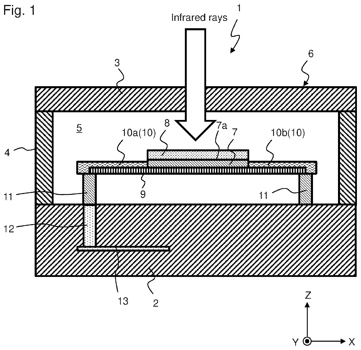
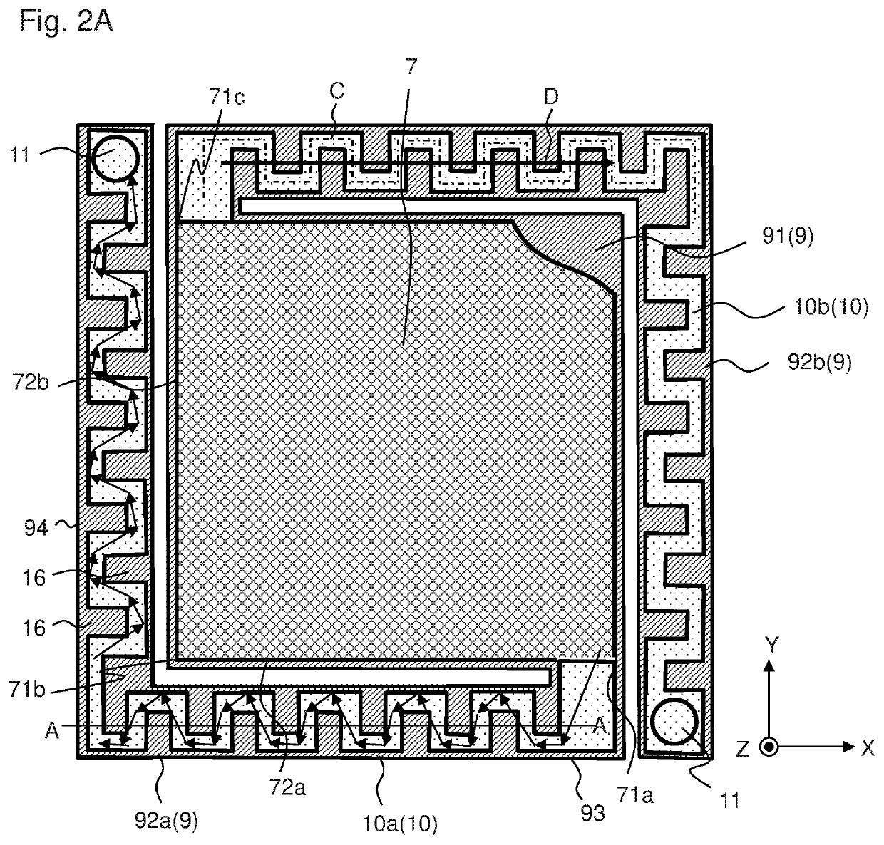
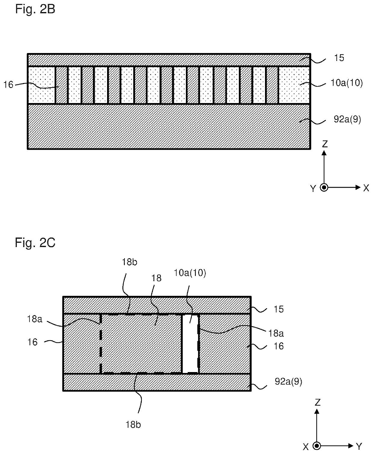
[0057]FIG. 1 is a schematic side view of infrared sensor 1 of the first embodiment of the present invention, FIG. 2A is a schematic plan view in the vicinity of the thermistor film, FIG. 2B is a sectional view of wiring layer 10 taken along line A-A in FIG. 2A, and FIG. 2C is a sectional view of wiring layer 10, as viewed in the X direction. Thermistor film 7 is partially omitted in FIG. 2A in order to show central portion 91 of support layer 9.
[0058]Infrared sensor 1 has first substrate 2, second substrate 3 that faces first substrate 2, as well as side walls 4 that connect first substrate 2 and second substrate 3. Second substrate 3 is a window substrate into which infrared rays enter. First substrate 2, second substrate 3 and side walls 4 form tightly closed inner space 5. Thermistor film 7 is housed in inner space 5. Inner space 5 is at a negative pressure or forms a vacuum.
[0059]That is, first substrate 2, second substrate 3 and side walls 4 form tightly closed vacuum housing 6...
second embodiment
[0072]FIG. 5A is a schematic plan view in the vicinity of thermistor film 7 of the infrared sensor of the second embodiment, and FIG. 5B shows a sectional view of wiring layer 20 taken along line A-A in FIG. 5. Here, the difference from the first embodiment will be mainly described. Configurations and effects that are not explained are the same as those of the first embodiment.
[0073]In the present embodiment, wiring layer 20 is separated or divided in the thickness direction (the Z direction) by separating layer 17. First wiring layer 21 is formed on support layer 9 (first arm portion 92a and second arm portion 92b), separating layer 17 is formed on first wiring layer 21, second wiring layer 22 is formed on separating layer 17, and second wiring layer 22 is covered with first insulating layer 15. Separating layer 17 is made of one or more materials selected from the group consisting of AlN, AlOx, diamond-like carbon, SiNx, SiOx, TaOx, and TiO2. Separating layer 17 may be made of the...
third embodiment
[0076]FIG. 6A shows a schematic plan view in the vicinity of thermistor film 7 of the infrared sensor of the third embodiment, FIG. 6B shows an enlarged view of portion A in FIG. 6, and FIG. 6C shows a sectional view of portion A, as viewed in the X direction. Here, the difference from the first embodiment will be mainly described. Configurations and effects that are not explained are the same as those of the first embodiment.
[0077]In the present embodiment, wiring layer 30 is separated or divided in the width direction by separating layers 31. More specifically, wiring layer 30 is separated or divided in the Y direction by separating layers 31 in first portion 93 of first arm portion 92a and is separated or divided in the X direction by separating layers 31 in second portion 94. First to fourth wiring layers 30a to 30d that extend in parallel with each other are formed on support layer 9 (first arm portion 92a), with first separating layer 31a being provided between first wiring la...
PUM
| Property | Measurement | Unit |
|---|---|---|
| wave length | aaaaa | aaaaa |
| electric resistance | aaaaa | aaaaa |
| temperature | aaaaa | aaaaa |
Abstract
Description
Claims
Application Information
 - R&D
- Intellectual Property
- Life Sciences
- Materials
- Tech Scout
- Unparalleled Data Quality
- Higher Quality Content
- 60% Fewer Hallucinations
Browse by: Latest US Patents, China's latest patents, Technical Efficacy Thesaurus, Application Domain, Technology Topic, Popular Technical Reports.
© 2025 PatSnap. All rights reserved.Legal|Privacy policy|Modern Slavery Act Transparency Statement|Sitemap|About US| Contact US: help@patsnap.com


