
Oil supply device for engine

a technology for oil supply devices and engines, which is applied in the direction of machines/engines, mechanical equipment, non-mechanical valves, etc., can solve the problems of excessive hydraulic pressure, oil may not be supplied to the entire oil supply passage, and oil may not be supplied to the pressure chamber in sufficient quantity, so as to shorten the time

Active Publication Date: 2020-08-11
MAZDA MOTOR CORP
View PDF25 Cites 1 Cited by
  • Summary
  • Abstract
  • Description
  • Claims
  • Application Information

AI Technical Summary

Benefits of technology

[0011]In view of the above, an object of the present invention is to provide an oil supply device for an engine, which enables to shorten a period of time required until an actual hydraulic pressure reaches a target hydraulic pressure, and to perform stable control of a hydraulically operated device in an early stage.
[0013]According to the present invention, it is possible to speedily cause an actual hydraulic pressure to reach a target hydraulic pressure when an engine is started in a cold state in which the oil viscosity is high, and to perform stable control of a hydraulically operated device in an early stage.

Problems solved by technology

Therefore, oil may not be supplied to the entirety of an oil supply passage.
As a result, a situation occurs such that oil is sufficiently supplied to a main gallery where a hydraulic pressure sensor is provided, and an excessively large actual hydraulic pressure is detected by the hydraulic pressure sensor regardless that oil is not sufficiently supplied to a pressure chamber of an oil pump provided on an oil supply passage downstream of the main gallery.
In this case, even when an oil control valve is controlled in such a manner as to lower the actual hydraulic pressure to a target hydraulic pressure by feedback control, oil may not be sufficiently supplied to the pressure chamber.
As a result, the oil pump may fail to adjust the discharge amount of oil, and may be incapable of lowering the actual hydraulic pressure.
However, in this case, the control amount of the oil pump for lowering the actual hydraulic pressure is excessively large.
As a result, the actual hydraulic pressure may be sharply lowered below the target hydraulic pressure, and the discharge amount of the oil pump may excessively decrease.
Therefore, when the discharge amount of the oil pump excessively decreases, a sufficient amount of oil may not be supplied to the pressure chamber, and the oil pump may be brought to a state in which the discharge amount is not adjustable.
In this case, even when the oil control valve is controlled to raise the excessively low actual hydraulic pressure to the target hydraulic pressure, the actual hydraulic pressure may not easily rise to the target hydraulic pressure.
However, in this case, the control amount of the oil pump for raising the actual hydraulic pressure is excessively large.
As described above, when feedback control is applied when an engine is started in a cold state, hunting by the actual hydraulic pressure may increase, and a long time may be required until the actual hydraulic pressure reaches the target hydraulic pressure.
As a result, it may be impossible to perform stable control of a hydraulically operated device such as a hydraulic VVT mechanism in an early stage.
Therefore, it may be impossible to solve the aforementioned drawbacks when an engine is started in a cold state.

Method used


Image

  • Oil supply device for engine
  • Oil supply device for engine
  • Oil supply device for engine

Examples


Embodiment Construction

[0028]In the following, an exemplary embodiment is described in detail on the basis of the drawings.

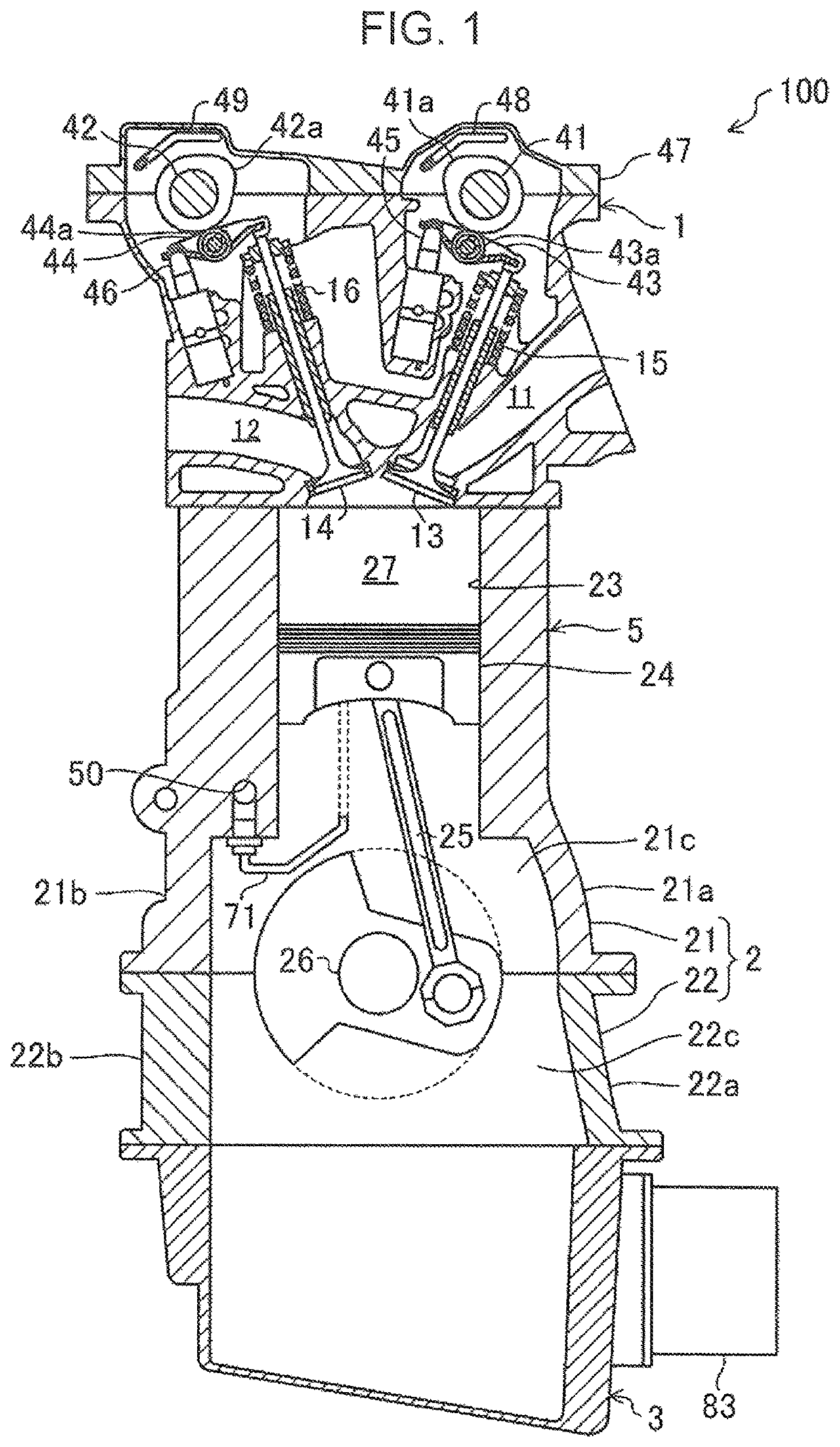
[0029]FIG. 1 is a schematic sectional view of an engine 100 taken along a plane including an axis of a cylinder. In the present specification, for the convenience of explanation, the axis direction of a cylinder is referred to as an up-down direction, and the cylinder array direction is referred to as a front-rear direction. Further, the side of the engine 100 opposite to a transmission in the cylinder array direction is referred to as a front side, and the transmission side is referred to as a rear side.

[0030]The engine 100 is an in-line 4-cylinder engine configured such that four cylinders are aligned in a predetermined cylinder array direction. The engine 100 includes a cylinder head 1, a cylinder block 2 mounted on the cylinder head 1, and an oil pan 3 mounted on the cylinder block 2.

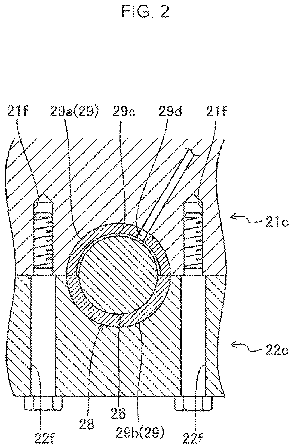
[0031]The cylinder block 2 includes an upper block 21 and a lower block 22. The lower block 22 is ...


PUM


Abstract

A controller sets a target hydraulic pressure from a required hydraulic pressure of a hydraulically operated device according to an operating condition of an engine. The controller causes an oil control valve to perform feedback control of the discharge amount of an oil pump in such a manner that an actual hydraulic pressure detected by a hydraulic pressure sensor coincides with the target hydraulic pressure. The controller executes feedback control after executing fixed duty control of setting a duty ratio of the oil control valve to a fixed duty ratio for a predetermined period of time from start of the engine.

Description

FIELD OF THE INVENTION[0001]The present invention relates to an oil supply device for an engine.BACKGROUND ART[0002]Conventionally, there is known an oil supply device for supplying oil to various parts of an engine.[0003]Japanese Patent No. 5,168,372 discloses a technique, in which the amount of oil to be supplied to bearing portions such as a crank bearing is regulated by a flow rate adjustment valve in such a manner that the oil pressure of a variable valve train mechanism reaches a target pressure or more when an engine is started to secure operability of the variable valve train mechanism from start of the engine.[0004]Japanese Unexamined Patent Publication No. 2014-199011 discloses a technique, in which a plurality of hydraulically operated devices (hydraulic VVT mechanisms and valve stop devices) are provided, a maximum required hydraulic pressure out of the required hydraulic pressures of the hydraulically operated devices is set as a target hydraulic pressure according to a...

Claims


Application Information

Patent Timeline
Patent Type & Authority Patents(United States)
IPC IPC(8): F01L1/344F01M11/10F01L1/24F01L13/00F01L9/02F01M1/16F01M1/02F02F7/00F01L1/18F01L1/053F01L9/10
CPCF01M1/16F01L13/0005F01L1/3442F01L9/02F01M1/02F01L1/2405F01M11/10F01L2250/04F16N2250/36F01L2810/02F01L2001/34426F01L2001/3443F01L2250/02F01L1/185F01L2305/00F01L2800/01F01L2001/34423F01L2001/0537F02F7/0053F01L9/10
Inventor HASHIMOTO, MASANORIOKAZAWA, HISASHI
Owner MAZDA MOTOR CORP
Learn More