Drainage system and vacuum pump for intrauterine vacuum therapy

a vacuum pump and drainage system technology, applied in the field of drainage system and vacuum pump for intrauterine vacuum therapy, can solve the problem of no special vacuum bandage system or drain, and achieve the effect of reducing the risk of perforation of the uterus during the advance of the fluid-collecting elemen

Active Publication Date: 2020-07-28
LOHMANN & RAUSCHER
View PDF17 Cites 1 Cited by
  • Summary
  • Abstract
  • Description
  • Claims
  • Application Information

AI Technical Summary

Benefits of technology

[0037]The tube or the tubular cavity terminates at the distal end within the fluid-collecting element. In this

Problems solved by technology

No special vacuum bandage systems or drains exi

Method used


Image

  • Drainage system and vacuum pump for intrauterine vacuum therapy
  • Drainage system and vacuum pump for intrauterine vacuum therapy
  • Drainage system and vacuum pump for intrauterine vacuum therapy

Examples


Embodiment Construction

[0074]Hereinafter, the invention is explained based on figures, which illustrate embodiments.

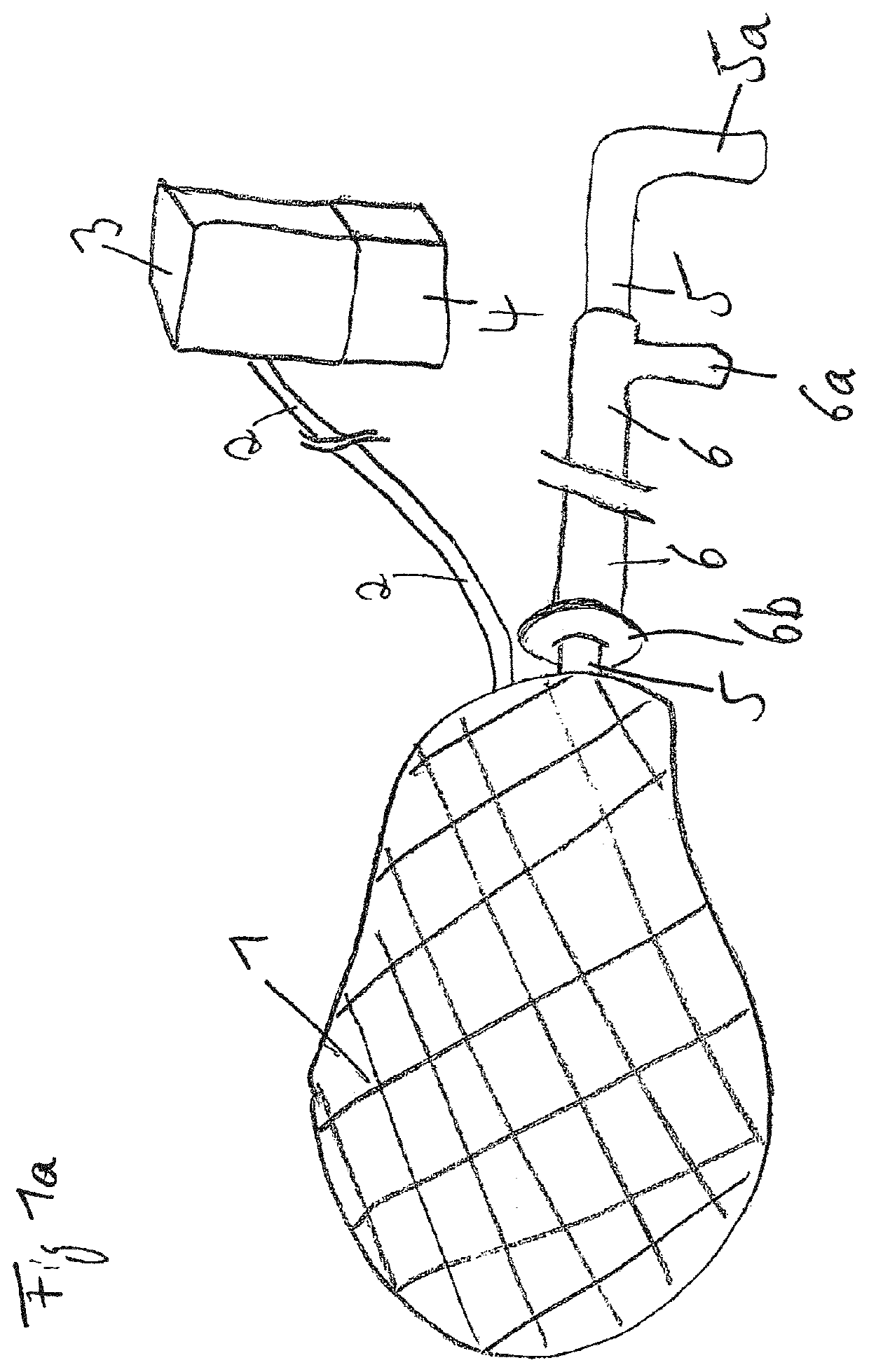
[0075]FIG. 1a is a top view of fluid-collecting element (1) in a merely suggested pear-shape. It is fluid-conductively connected to a tubular fluid-communicating element (2), which is fluid-conductively connected to a secretion collection vessel (3) having a vacuum generating pump (4). Into the collection element (1), a guide-rod (5) with handle (5a) is introduced, which is situated in a sheath (6) that is movable on it, the latter is also at the proximal end with a grip (6a) and ends at the distal end in a disc-like plate (6b) for pushing the fluid-collecting element (1) forward.

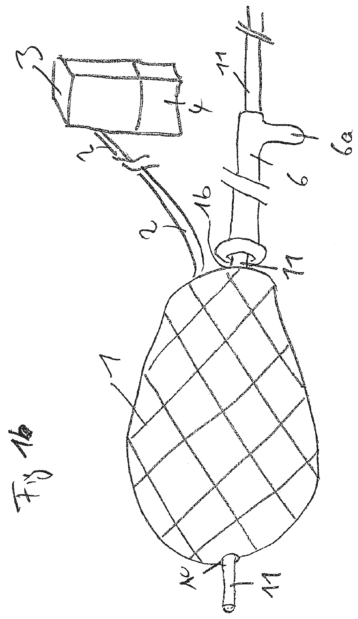
[0076]FIG. 1b, like Figure, 1 is a top view of fluid-collecting element (1) in a merely suggested pear shape. It is fluid-conductively connected to a tubular fluid-communicating element (2), which is fluid-conductively connected to a secretion collection vessel (3) having a vacuum-generating pump (4). In collection ...


PUM


Abstract

A device for intrauterine vacuum therapy includes a pear-shaped fluid-collecting element and a fluid-communicating element. The fluid-collecting element defines an inlet opening at the proximal end and a tubular cavity for receiving a removable guide-rod during transvaginal insertion into a uterine cavity. The fluid-communicating element has a perforated distal end fixed within the fluid-collecting element outside the tubular cavity and has a proximal end adapted for connection to a vacuum-generating system. A method of treating an intrauterine wound or infection includes transvaginally inserting a drain into a uterine cavity and applying a negative pressure to the drain such that the uterus collapses and the inner wall is aspirated against the drain.

Description

CROSS-REFERENCE TO RELATED APPLICATIONS[0001]This is a national phase application from PCT Patent Application Serial No. PCT / EP2015 / 000756 filed on Apr. 10, 2015, which claims priority to German Patent Application Serial No. 10 2014 005 679.1 filed on Apr. 16, 2014, each of which is incorporated herein by reference in its entirety.STATEMENT REGARDING FEDERALLY SPONSORED RESEARCH OR DEVELOPMENT[0002]Not applicable.BACKGROUND OF THE INVENTION[0003]Negative pressure therapy (vacuum therapy, vacuum sponge therapy, low pressure therapy) is used for treatments of external wounds. An open-cell polyurethane foam or another open-cell wound filler (e.g. cotton gauze) is inserted into the wound and occluded using a film. Subsequently, a vacuum is applied to this dressing using a vacuum-generating system (for example an electronic vacuum pump). In this way, wound secretion and wound edema can be permanently drained over several days, and infected wounds can be cleansed. Blood circulation is imp...

Claims


Application Information

Patent Timeline
IPC IPC(8): A61M1/00A61B17/42A61B17/12A61B1/012A61B1/303
CPCA61M1/0037A61B17/42A61M1/0088A61B17/12A61B2017/4216A61B2017/12004A61B2217/005A61M2210/1433A61B1/012A61B1/303A61M1/75A61M1/98A61M1/916
Inventor LOSKE, GUNNAR
Owner LOHMANN & RAUSCHER
Why Eureka
Try Eureka