
Single-piece cover for an electronic device

a single-piece cover and electronic device technology, applied in the field of wireless electronic devices, can solve the problem of bulky electronic devices, and achieve the effect of more economical manufacturing

Active Publication Date: 2020-07-07
SAGEMCOM BROADBAND
View PDF11 Cites 2 Cited by
  • Summary
  • Abstract
  • Description
  • Claims
  • Application Information

AI Technical Summary

Benefits of technology

[0011]In the meaning of the present application, the term “single-piece” refers to a set of components that are secured to one another in such a manner as to be able to be handled together without the risk of the components becoming separated. In the meaning of the present application, a cover is an outer shell of the product, a part that is visible on the finished product without disassembly and that protects internal components from the outside. A cover therefore provides mechanical protection (from impacts, handling) and depending on the design (without holes), the cover may protect against projections of water, dust, and electrical / electrostatic impulses.
[0022]The use of proven standard connectors makes it possible to reduce supply costs and improves the reliability of the electrical connection.

Problems solved by technology

The multiplicity of the sub-elements making up the electronic device requires numerous assembly operations that affect manufacturing costs of the electronic device as well as logistical costs (storage, transport to the place of production, distribution to the assembly station) of the sub-elements.
These numerous sub-elements also make existing electronic devices bulky, whereas consumers seek equipment that is increasingly compact.

Method used


Image

  • Single-piece cover for an electronic device
  • Single-piece cover for an electronic device

Examples


Embodiment Construction

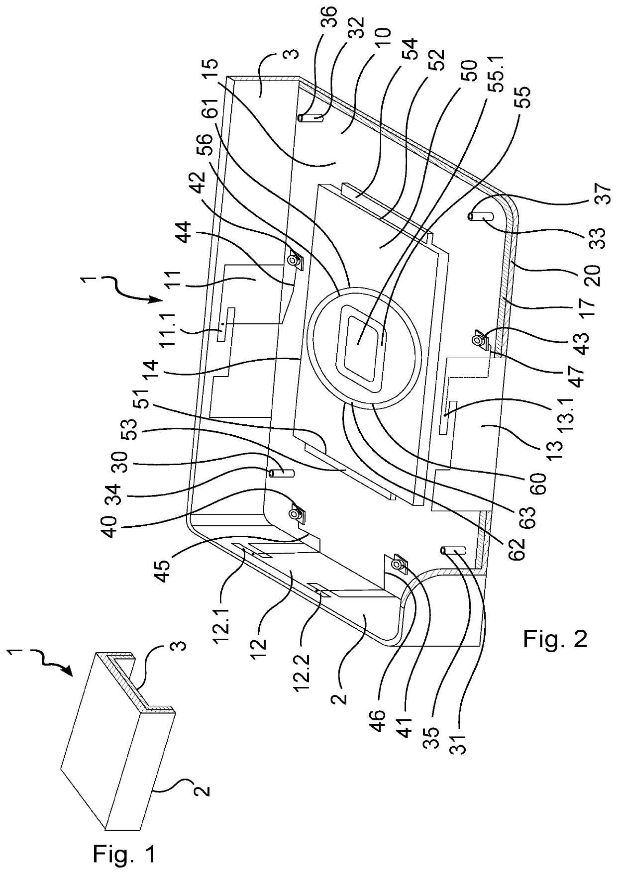
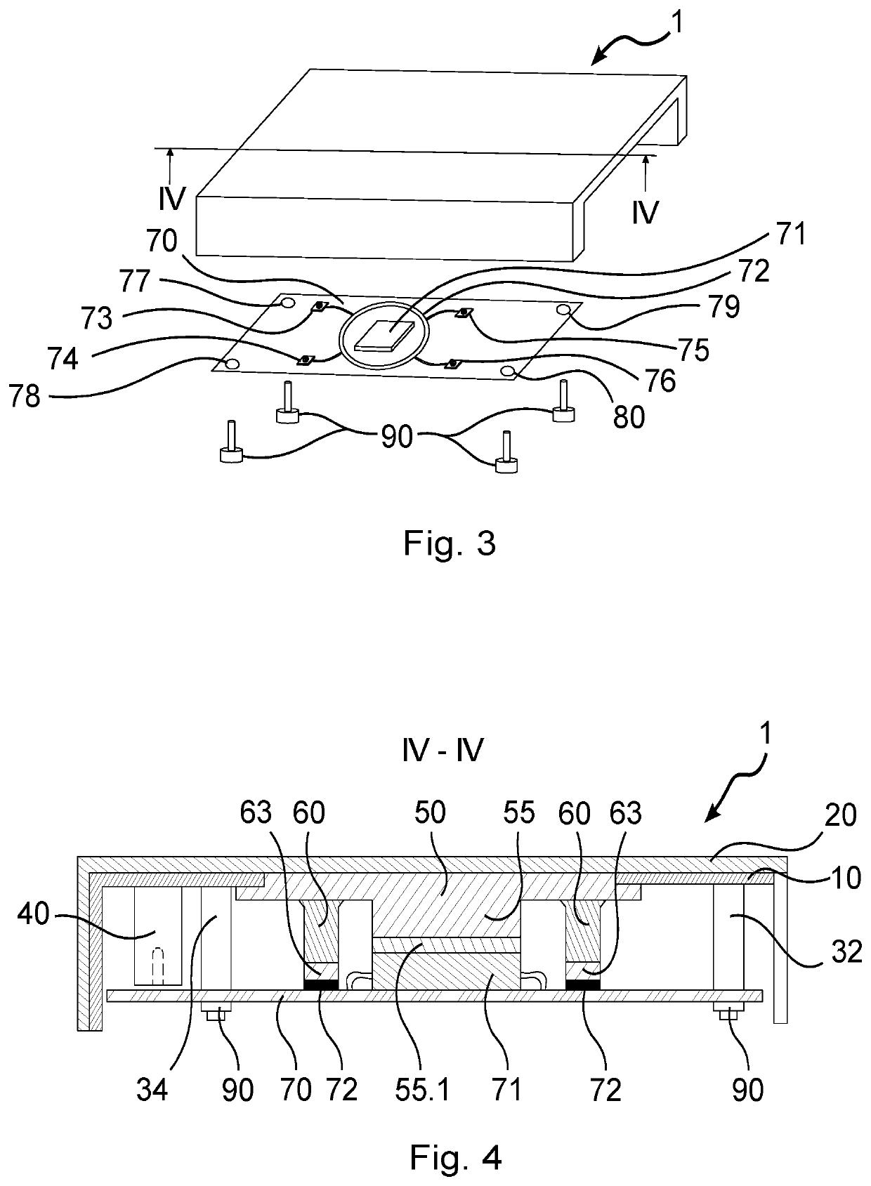
[0033]With reference to FIGS. 1 and 2, the single-piece cover of the invention, generally given reference 1, is substantially of rectangular box shape and includes a top wall and three adjacent side walls in such a manner that the box has a bottom face 2 that is open and a rear face 3 that is also open.

[0034]The cover 1 comprises an antenna structure 10, made of copper, substantially of rectangular shape. The structure 10 has at its periphery three folded-back flaps 11, 12, and 13, and an opening 14 of rectangular shape at its center. An inside surface 15 of the structure 10 defines a reception housing 4 for receiving an electronic device.

[0035]The cover 1 also includes a passive heatsink 50, of rectangular shape, housed in the opening 14 of the structure 10 in order to have one face flush with an outside surface 17 of the structure 10 at the top wall of the structure 10. The shorter sides 51 and 52 of the heatsink 50 have rims 53 and 54 projecting from the opening 14 in order to be...


PUM

PropertyMeasurementUnit
electrically-insulatingaaaaaaaaaa
compressible conductiveaaaaaaaaaa
mechanical connectionaaaaaaaaaa

Abstract

A single-piece cover for an electronic device, said cover including: a heat sink; an antenna; a shielding screen; an electrically insulating synthetic material forming outer surfaces of the cover.

Description

FIELD OF THE INVENTION[0001]The present invention relates to the field of wireless electronic communication devices, and more particularly to the boxes of wireless electronic devices of the router or gateway type.BACKGROUND OF THE INVENTION[0002]Electronic devices exist that comprise a box housing specifically an electronic card that is electrically connected to an antenna, and a heatsink for dissipating the heat produced by one or more electronic components of the card while they are in operation. The electronic card also receives an electromagnetic shielding screen and a mechanical protection cover on which the decorative finishes of the device are generally carried.[0003]The multiplicity of the sub-elements making up the electronic device requires numerous assembly operations that affect manufacturing costs of the electronic device as well as logistical costs (storage, transport to the place of production, distribution to the assembly station) of the sub-elements.[0004]These nume...

Claims


Application Information

Patent Timeline
Patent Type & Authority Patents(United States)
IPC IPC(8): H05K9/00H01Q1/52H05K7/20
CPCH05K9/0026H05K9/0024H05K7/20445H01Q1/526H05K7/20436H05K9/0032
Inventor SABATIER, PIERRESUSINI, DOMINIQUEALEGRE, THIERRYDEJARDIN, ROMAIN
Owner SAGEMCOM BROADBAND
Learn More