
Remote maintenance system and relay unit

a maintenance system and relay technology, applied in the field of remote maintenance system and relay unit, can solve the problems of limited installation place, inability to use the apparatus anywhere, and insufficient long-term use of the apparatus, and achieve the effect of long-term operation

Active Publication Date: 2020-07-07
NIHON KOHDEN CORP
View PDF53 Cites 0 Cited by
  • Summary
  • Abstract
  • Description
  • Claims
  • Application Information

AI Technical Summary

Benefits of technology

Enables remote maintenance of medical devices in various environments without relying on commercial power, ensuring long-term operation and timely notification of issues, even in remote or size-constrained installations.

Problems solved by technology

Therefore, the installation place is limited, and such an apparatus cannot be used anywhere.
In this case, however, a countermeasure against battery rundown is required, and therefore such an apparatus is inadequate in a long-term use.
In the case where such an apparatus is installed in a remote place, battery replacement cannot be frequently performed.
Consequently, there remain problems to be solved.
In the case where the size of a medical device itself is large, the apparatus cannot house the medical device.
However, a professional company which manages the AED cannot use the apparatus in maintenance of the AED.
When, for example, the AED itself breaks down, moreover, alert information cannot be sent and cannot be informed.
Furthermore, there is a possibility that, when the AED performs a process such as reception of information, the user must wait to use the AED.
Therefore, the system cannot be used in an environment where the installation place of a medical device is not considered.
The check item may include communication between the medical device and the relay unit, and when the communication is disabled, the determiner may determine that the communication is abnormal.

Method used


Image

  • Remote maintenance system and relay unit
  • Remote maintenance system and relay unit
  • Remote maintenance system and relay unit

Examples


Embodiment Construction

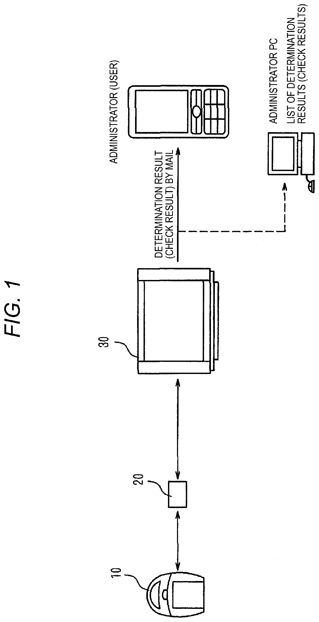
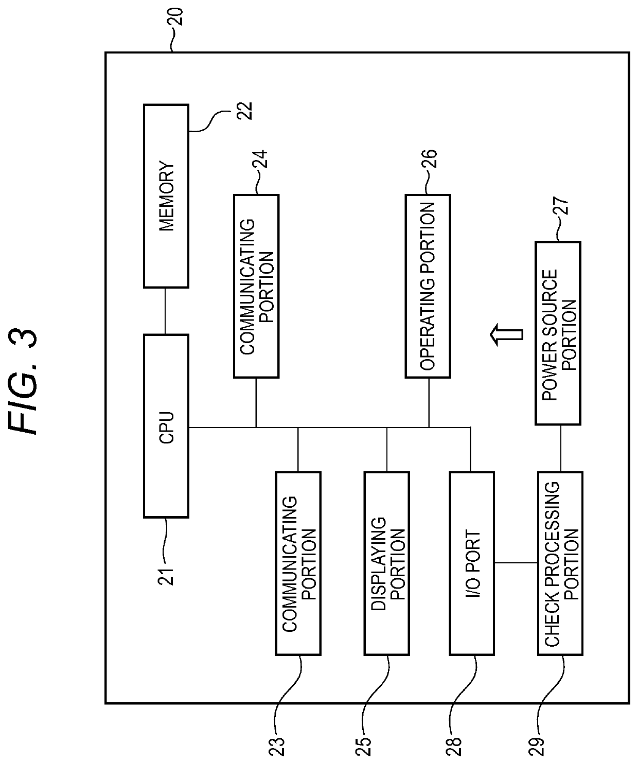
[0043]Hereinafter, embodiments of a remote maintenance system and a relay unit of the invention will be described with reference to the accompanying drawings. In the figures, the identical components are denoted by the same reference numerals, and duplicated description will be omitted. FIG. 1 is a diagram of the embodiment of the remote maintenance system of the invention. The remote maintenance system includes a medical device 10, a relay unit 20, and a maintenance center device 30. Usually, the medical device 10 and the relay unit 20 are used in a plural number. Basically, the medical device 10 corresponds to the relay unit 20 in a one-to-one relationship. Alternatively, the relay unit 20 may have a configuration to correspond to a plurality of medical devices 10.

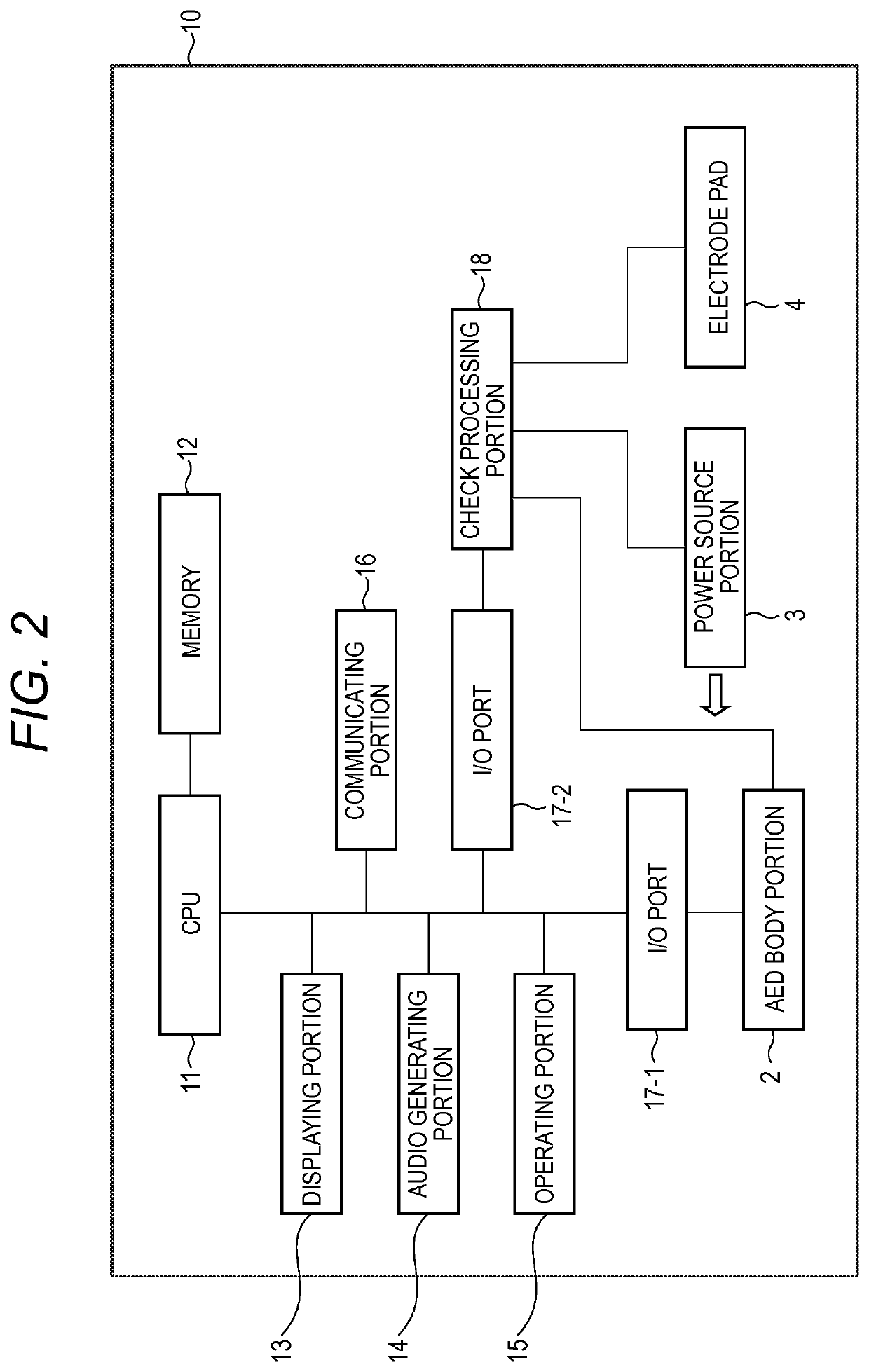
[0044]As the medical device 10 in the embodiment, an AED (Automatic External Defibrillator) having the configuration shown in FIG. 2 is exemplified. The medical device 10 includes a CPU 11 which controls various portions...


PUM


Abstract

A remote maintenance system includes: a medical device which includes: a first power source; a first power source controller which controls an ON / OFF operation of the first power source; a checker which checks a check item; and a first communicator which transmits first information including a result of a check by the checker; and a relay unit which includes: a second power source; a second power source controller which automatically controls an ON / OFF operation of the second power source; and a second communicator which communicates with the first communicator and which receives the first information from the first communicator.

Description

BACKGROUND OF THE INVENTION[0001]The present invention relates to a remote maintenance system which checks and manages states of various medical devices, and also to a relay unit which is to be used in such a remote maintenance system.[0002]As a related-art apparatus of this kind, there is an apparatus which detects extraction or abnormal state of an emergency device disposed in a case, and which notifies a managing device (see JP-A-2007-58442, JP-A-2007-244804 and JP-A-2006-043270). In such an apparatus, it is necessary to monitor whether the emergency device is extracted, and hence constant monitoring is required. This necessitates a power supply such as a commercial power supply. Therefore, the installation place is limited, and such an apparatus cannot be used anywhere. It may be contemplated that such an apparatus is configured so as to use a large battery in place of a commercial power supply. In this case, however, a countermeasure against battery rundown is required, and the...

Claims


Application Information

Patent Timeline
Patent Type & Authority Patents(United States)
IPC IPC(8): G06K7/01H04L12/12G06F11/30G16H40/40
CPCG16H40/40H04L12/12G06F11/3013G06F11/3055Y02D50/40Y02D30/50
Inventor WAKABAYASHI, TSUTOMUTEZUKA, SHINJINAKAYAMA, TADASHI
Owner NIHON KOHDEN CORP
Learn More