3D building modeling systems

a building modeling and building technology, applied in the field of three-dimensional building representations, can solve the problems of inability to model complex roof structures, high degree of skill, and limitations of conventional approaches for building complex roofs, and achieve the effect of less training and creating complex roof structures

Active Publication Date: 2020-07-07
AURORA SOLAR
View PDF3 Cites 10 Cited by
  • Summary
  • Abstract
  • Description
  • Claims
  • Application Information

AI Technical Summary

Benefits of technology

[0006]Described herein is a process and system for constructing three-dimensional (3D) representations of roof structures. Embodiments described herein can create representations of roof structures of arbitrary complexity and can create representations of dependent roof structures such as dormers. Embodiments described herein overcome the limitations of the conventional methods and can create representations of roof structures that conventional methods cannot create, such as roofs with edges that are not coplanar, roofs with faces that do not connect to exterior edges, roofs composed of sub-structures, or roofs with dependent structures such as dormers. Finally, the embodiments described herein, allow users to create complex roof structure much faster, and with less training required, than conventional methods.

Problems solved by technology

However, conventional approaches have limitations in constructing complex roofs.
All of these solutions have in common that they cannot model complex roof structures because they do not support for roof structures where perimeter edges are at different heights or roof structures that contain pitch changes.
Additionally, these systems are usually general-purpose CAD tools that are complicated to use and thus require a lot of effort and a high degree of skill.
This limits their use for applications that require a fast turn-around time and its use by unsophisticated users.

Method used


Image

  • 3D building modeling systems
  • 3D building modeling systems
  • 3D building modeling systems

Examples


Embodiment Construction

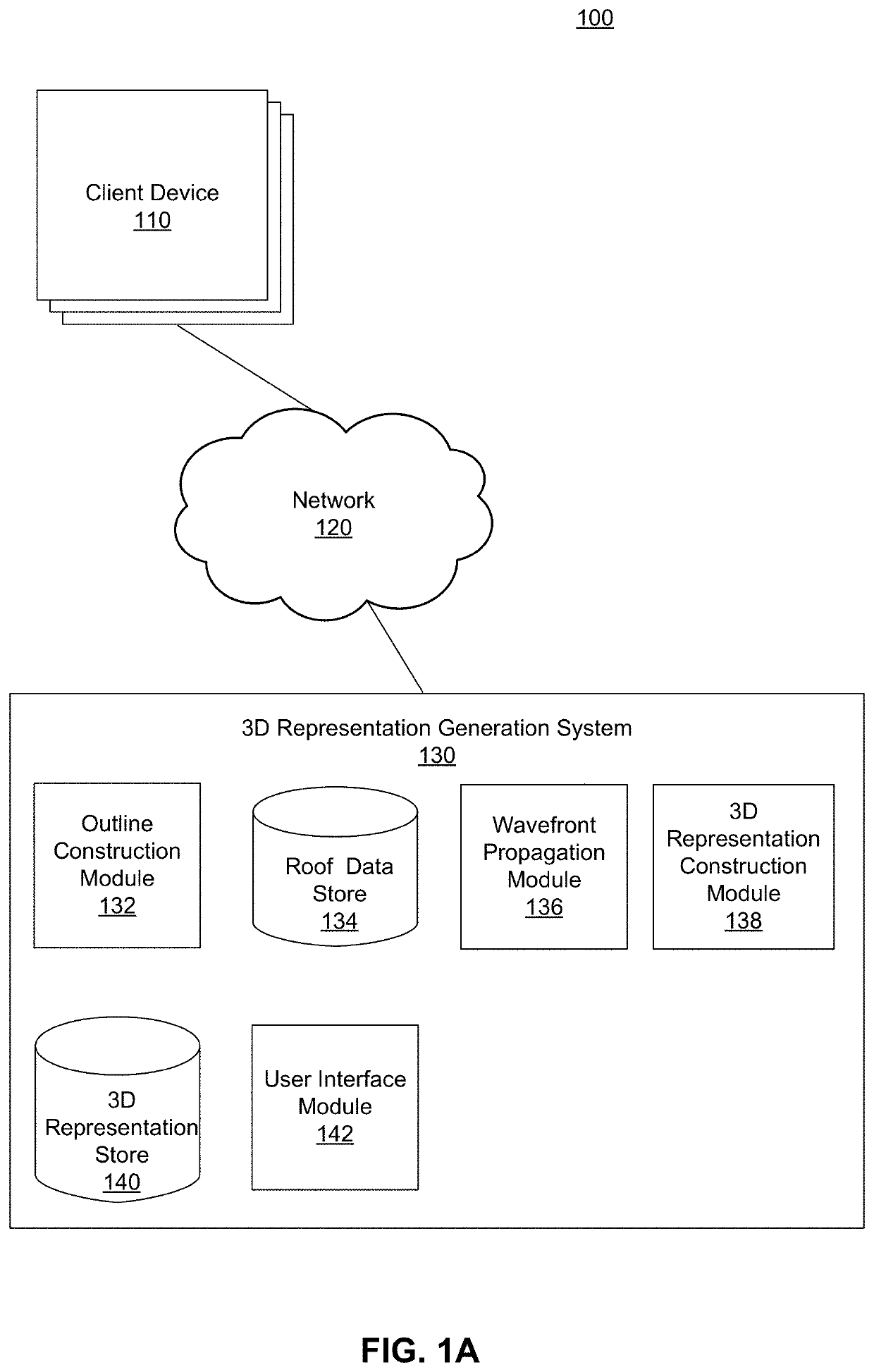
[0019]FIG. 1A illustrates a computing environment 100 for generating three-dimensional (3D) building representations, according to one embodiment. The environment includes entities such as client device 110, a 3D representation generation system 130, and a network 120. The network 120 connects the client devices 110 and the 3D representation generation system 130. In the illustrated example, only one 3D representation generation system is shown, but there may be multiple instances of the 3D representation generation system.

[0020]Client devices 110 include computing devices such as mobile devices (e.g., smartphones or tablets with operating systems such as Android or Apple iOS), laptop computers, desktop computers, or any other type of network-enabled device that enable users to interact with the 3D representation generation system 130. For example, the client devices 110 enable users to receive 3D representation generation services from the 3D representation generation system 130. A...


PUM


Abstract

Described herein is a process and system for constructing three-dimensional (3D) representations of buildings. The 3D representations of buildings are semantic models that include roof nodes, roof edges, as well as roof faces with associated properties (e.g., pitch, azimuth). The system receives a 2D representation such as a roof outline including nodes connected by edges and associated data such as a height value, a pitch value, an independent structure, or a dependent structure. The system determines height values where a building structure changes. The system propagates a wavefront representing a cross-section of the building to the height values to generate 3D model edges. The 3D representation is generated based on the 3D model edges. The system can create 3D representations of buildings including roof structures of arbitrary complexity and can create representations of dependent roof structures such as dormers.

Description

CROSS-REFERENCE TO RELATED APPLICATION(S)[0001]This application claims the benefit of U.S. Provisional Application No. 62 / 544,694, filed Aug. 11, 2017, of which the subject matter is incorporated herein by reference in its entirety.BACKGROUND[0002]1. Technical Field[0003]The current application relates to constructing three-dimensional representations of building structures such as roofs.[0004]2. Background Information[0005]Constructing three-dimensional (3D) building structures such as roofs is useful and has many applications. However, conventional approaches have limitations in constructing complex roofs. Some solutions simplify the problem by modeling only roof planes of interest, for example by drawing an outline of a single roof face and assigning a pitch and an azimuth to it. Users may also manually create three-dimensional models in CAD software. In some cases, users may manually define an outline of a roof and use tools that convert a straight skeleton of the outline to 3D ...

Claims


Application Information

Patent Timeline
Patent Type & Authority Patents(United States)
IPC IPC(8): G06T17/05G06T17/20G06T15/00G06T19/20
CPCG06T17/05G06T17/20G06T15/005G06T19/20G06T2219/2021
Inventor HOPPER, CHRISTOPHERSTEVENS, MATTHEW
Owner AURORA SOLAR
Why Eureka
Try Eureka