
Apparatuses and methods for avoiding glitches when switching clock sources

a clock source and apparatus technology, applied in the direction of pulse technique, logic circuit characterised by logic function, generating/distributing signals, etc., can solve the problem of generating glitches or chopped signals on the clock output line, and achieve the effect of suppressing glitches

Active Publication Date: 2020-07-07
QUALCOMM INC
View PDF4 Cites 1 Cited by
  • Summary
  • Abstract
  • Description
  • Claims
  • Application Information

AI Technical Summary

Benefits of technology

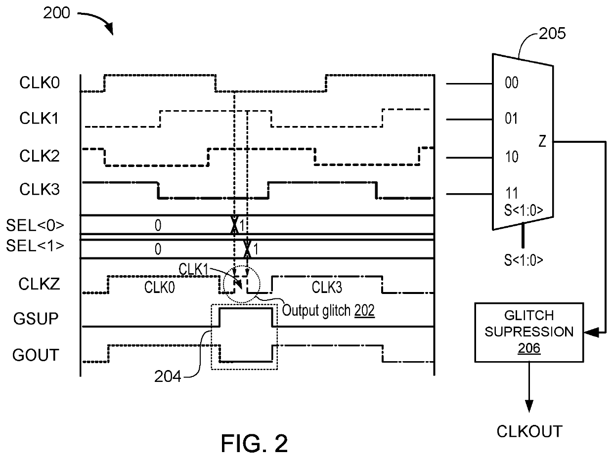
The present disclosure addresses how to prevent glitches when switching clock sources. The second embodiment of the disclosure provides a method for suppressing glitches during switches between clock input sources. This involves outputting a first clock signal, receiving a signal to switch from the first clock signal to a second clock signal, and then suppressing a glitch during the transition between the first and second clock signals. Finally, the second clock signal is outputted. Overall, this method allows for smoother and more reliable clock switching without glitches.

Problems solved by technology

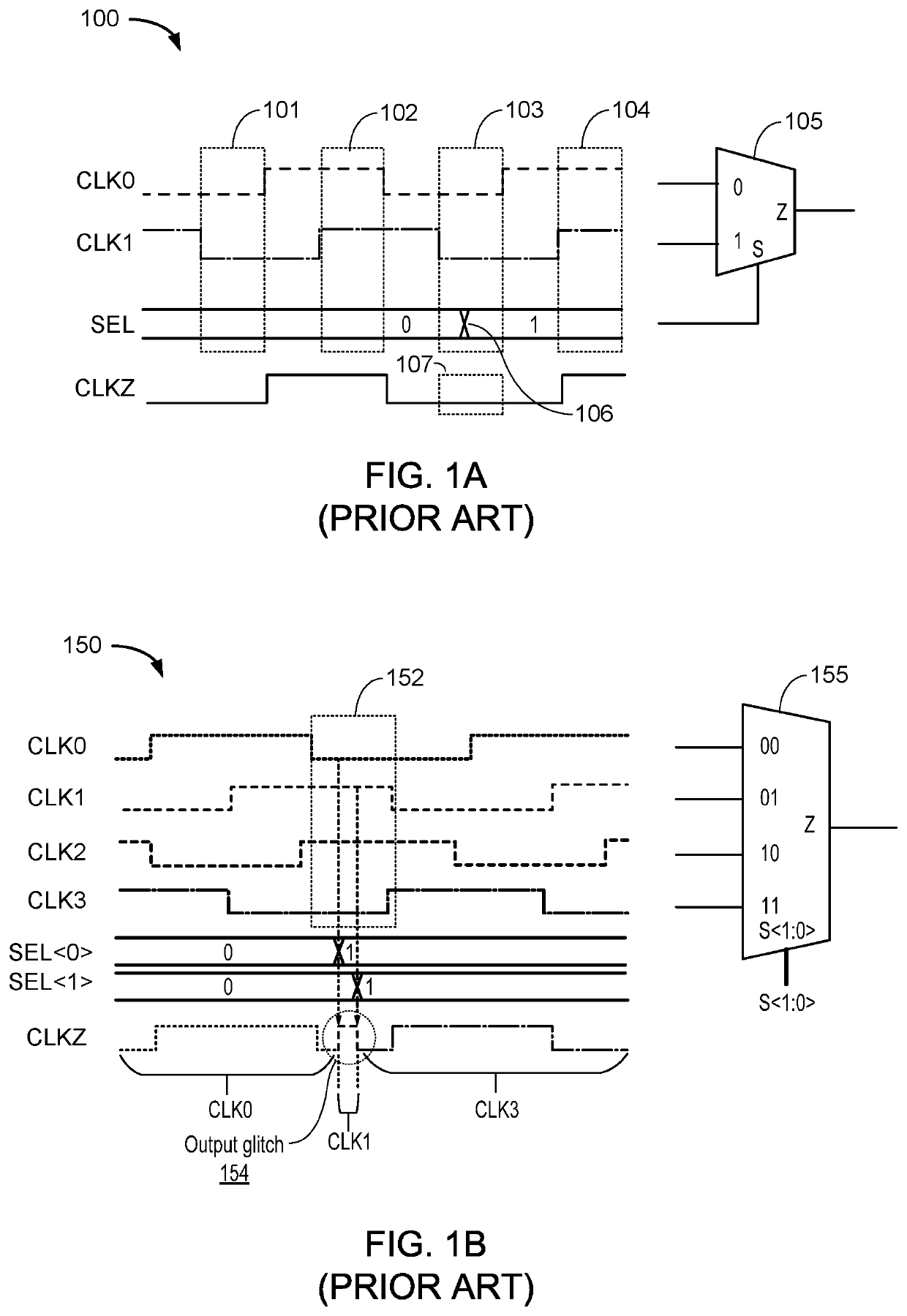
In either case, there is a chance of generating a glitch or chopped signal on the clock output line when one clock signal (e.g., at a first frequency) is changed to another clock signal (e.g., at a second frequency).

Method used


Image

  • Apparatuses and methods for avoiding glitches when switching clock sources
  • Apparatuses and methods for avoiding glitches when switching clock sources
  • Apparatuses and methods for avoiding glitches when switching clock sources

Examples


Embodiment Construction

[0018]Aspects of the present disclosure provide apparatuses, methods, processing systems, and computer readable mediums for avoiding glitches when switching clock sources.

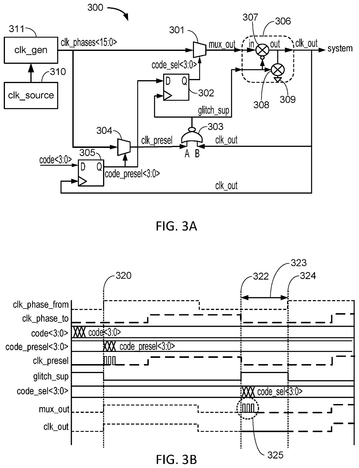
[0019]To solve the problem of glitches produced when switching between multiple inputs, especially by way of multiplexers, a glitch suppression circuit element may be added to a switching circuit, such as a clock switching circuit. In general terms, the glitch suppression circuit may be configured to output either a currently selected input from a multiplexer or the output may be tied to a ground to pull the resulting output signal low. Because many clock signals alternate between logical high (e.g., ‘1’) and logical low (e.g., ‘0’), connecting an output signal line to ground may emulate a logical low during a time interval. Moreover, the glitch suppression circuit may be compared to a logic circuit element so that the suppression of glitches is automatically achieved with minimal additional circuitry. The suppress...


PUM


Abstract

Certain aspects of the present disclosure provide an input clock switching system, including: a clock source configured to output a reference clock signal; a clock generator circuit connected to the clock source and configured to output a plurality of input clock signals based on the reference clock signal; an output clock multiplexer, configured to: receive the plurality of input clock signals; receive an output clock selection signal; and output a first clock signal, wherein the first clock signal is one of the input clock signals; and a glitch suppression circuit, configured to: receive the first clock signal; receive a glitch suppression signal; output a clock output signal, wherein the clock output signal is: the first clock signal when the glitch suppression signal is in a first state; and a logic low signal when the glitch suppression signal is in a second state.

Description

INTRODUCTION[0001]Aspects of the present disclosure relate to apparatuses and methods for avoiding glitches when switching clock sources.[0002]Electronic devices frequently rely on multiple clock signals (e.g., at different frequencies). For example, digital circuits used in microprocessors often have the capacity to select from a variety of available clock signals in order to match processing rate with demand while saving power when demand is reduced. Similarly, communications circuitry often relies on a variety of different frequency clock signals to create transmission and reception frequencies across different radio technologies (e.g., cellular and Bluetooth). In fact, generation and consumption of multiple clock signals is nearly ubiquitous in modern electronic devices.[0003]One simple type of clock switch is a multiplexer circuit, which takes two or more clock signal sources as inputs and includes selection circuitry to choose from the clock signal sources a single output. In ...

Claims


Application Information

Patent Timeline
Patent Type & Authority Patents(United States)
IPC IPC(8): G06F1/08G06F1/06H03K19/20
CPCG06F1/08G06F1/06H03K19/20H03K5/1252
Inventor HUANG, YUDANG, NAM
Owner QUALCOMM INC
Learn More