
Radon removal apparatus

a technology of radon gas removal and radon gas, which is applied in lighting and heating apparatus, ventilation systems, heating types, etc., can solve the problems of inability to have the blower mounted upright in an inline pipe system, radon gas is considered a health risk, and existing technology does not promote the most efficient mounting of the blower

Active Publication Date: 2020-06-23
WHOLESALE RADON DISTRIBUTION HLDG LLC
View PDF3 Cites 1 Cited by
  • Summary
  • Abstract
  • Description
  • Claims
  • Application Information

AI Technical Summary

Benefits of technology

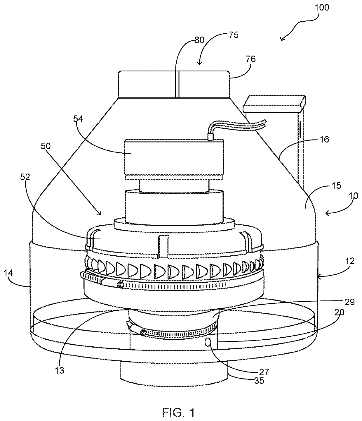
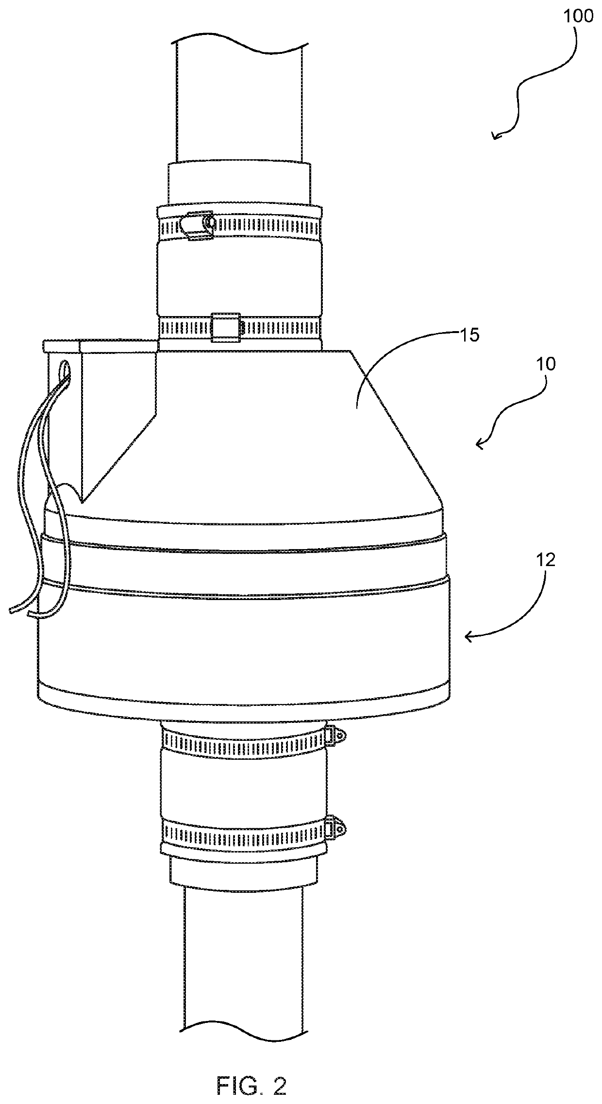
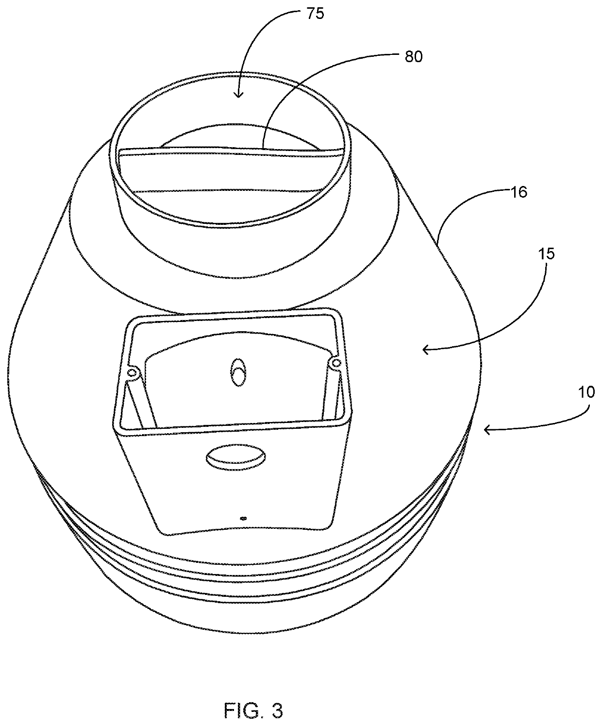
The present invention is a radon removal apparatus that can prevent radon from entering a building. It has a housing with a lower portion and an upper portion that are connected at the bottom, making it easy to connect to a pipe. The bottom of the housing has a raised section that can hold a blower assembly in a vertical position. The apparatus also has an exhaust opening with a cross member and a low voltage direct current motor to operate the vacuum impeller of the blower assembly. Overall, the apparatus can effectively remove radon from buildings and keep them safe from radon exposure.

Problems solved by technology

Radon gas is considered a health risk as it is typically the single largest contributor to an individuals background radiation dose.
One issue with existing radon removal fans is their inability to have the blower mounted in an upright position in an inline pipe system.
Existing technology does not promote the most efficient mounting of the blower and as such the removal efficiency.
Additionally, most radon fans are mounted outdoors and as such are subject to humidity and temperature changes.
The exposure to humidity and temperature changes results in accumulation of condensation in the system and existing technology lacks the elements to provide removal thereof.
Lastly, exit vents of existing radon fans have a velocity of air traversing therethrough that is sufficient to create noise during operation which can be undesirable for homeowners.

Method used


Image

  • Radon removal apparatus
  • Radon removal apparatus
  • Radon removal apparatus

Examples


Embodiment Construction

[0020]Referring now to the drawings submitted herewith, wherein various elements depicted therein are not necessarily drawn to scale and wherein through the views and figures like elements are referenced with identical reference numerals, there is illustrated a radon removal apparatus 100 constructed according to the principles of the present invention.

[0021]An embodiment of the present invention is discussed herein with reference to the figures submitted herewith. Those skilled in the art will understand that the detailed description herein with respect to these figures is for explanatory purposes and that it is contemplated within the scope of the present invention that alternative embodiments are plausible. By way of example but not by way of limitation, those having skill in the art in light of the present teachings of the present invention will recognize a plurality of alternate and suitable approaches dependent upon the needs of the particular application to implement the func...


PUM


Abstract

A radon gas removal apparatus that is operable to substantially inhibit the entrance of radon gas into a structure. The radon gas removal apparatus is operably coupled to an area to which the structure is superposed. A housing is further included wherein the housing has a lower portion and upper portion mateably coupled. A blower assembly is present within the housing and is mounted in a vertical upright position. The lower portion of the housing includes a bottom having a mount extending upward therefrom to which the blower assembly is operably coupled utilizing a coupling. A fluid aperture is present in the mount and is operable to facilitate the egression of accumulated fluid present at the bottom of the housing into a connected pipe. The housing further includes an air turbulence diffusion member present on an exit aperture formed in the upper portion of the housing.

Description

FIELD OF INVENTION[0001]The present invention relates generally to gas evacuation systems, more specifically but not by way of limitation, a radon removal apparatus that is operably coupled to an area underneath a residential or commercial structure wherein the radon removal apparatus functions to remove radon gas that accumulates underneath the structure and vent the gas to atmosphere.BACKGROUND[0002]Radon gas is a colorless, odorless and tasteless noble gas that is radioactive. Radon gas naturally occurs in small quantities as an intermediate step in the normal radioactive decay chains through which elements such as but not limited to thorium slowly decay into lead and other short-lived radioactive elements. Despite radon's short half-life, it is continuously being regenerated and as such its presence will remain long into the future. Radon gas is considered a health risk as it is typically the single largest contributor to an individuals background radiation dose. The presence of...

Claims


Application Information

Patent Timeline
IPC IPC(8): F24F7/06E02D31/00
CPCF24F7/06E02D31/008F24F7/065F24F8/70
Inventor GELINA, JAMEY
Owner WHOLESALE RADON DISTRIBUTION HLDG LLC
Learn More