Multifunctional breathable storage cabinet
a multi-functional, breathable technology, applied in the field of storage cabinets, can solve the problems of high wood consumption, heavy storage cabinets, and inconvenient transportation, and achieve the effects of reducing transportation costs, simple structure, and reducing space occupied during transportation
- Summary
- Abstract
- Description
- Claims
- Application Information
AI Technical Summary
Benefits of technology
Problems solved by technology
Method used
Image
Examples
embodiment 1
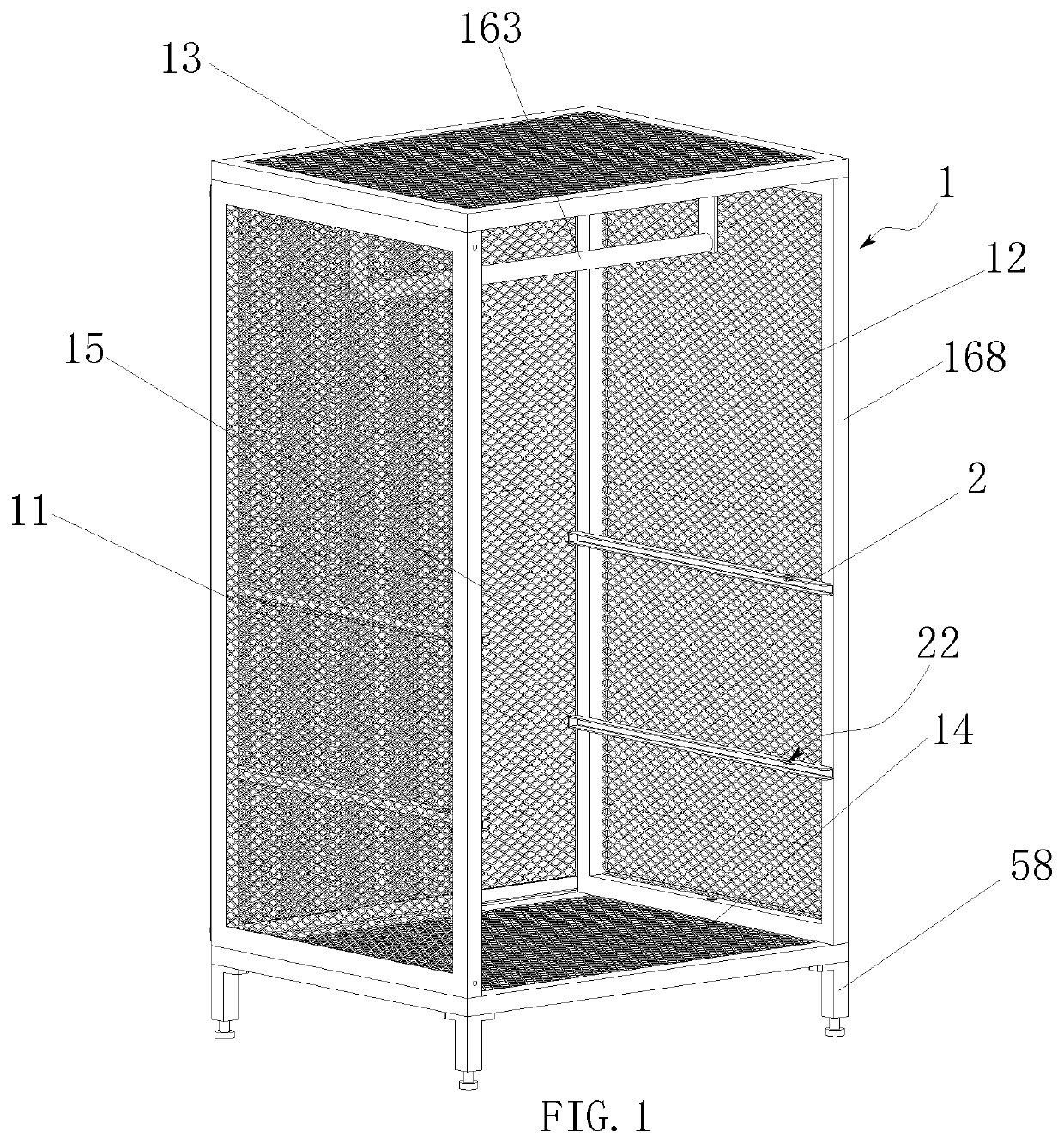
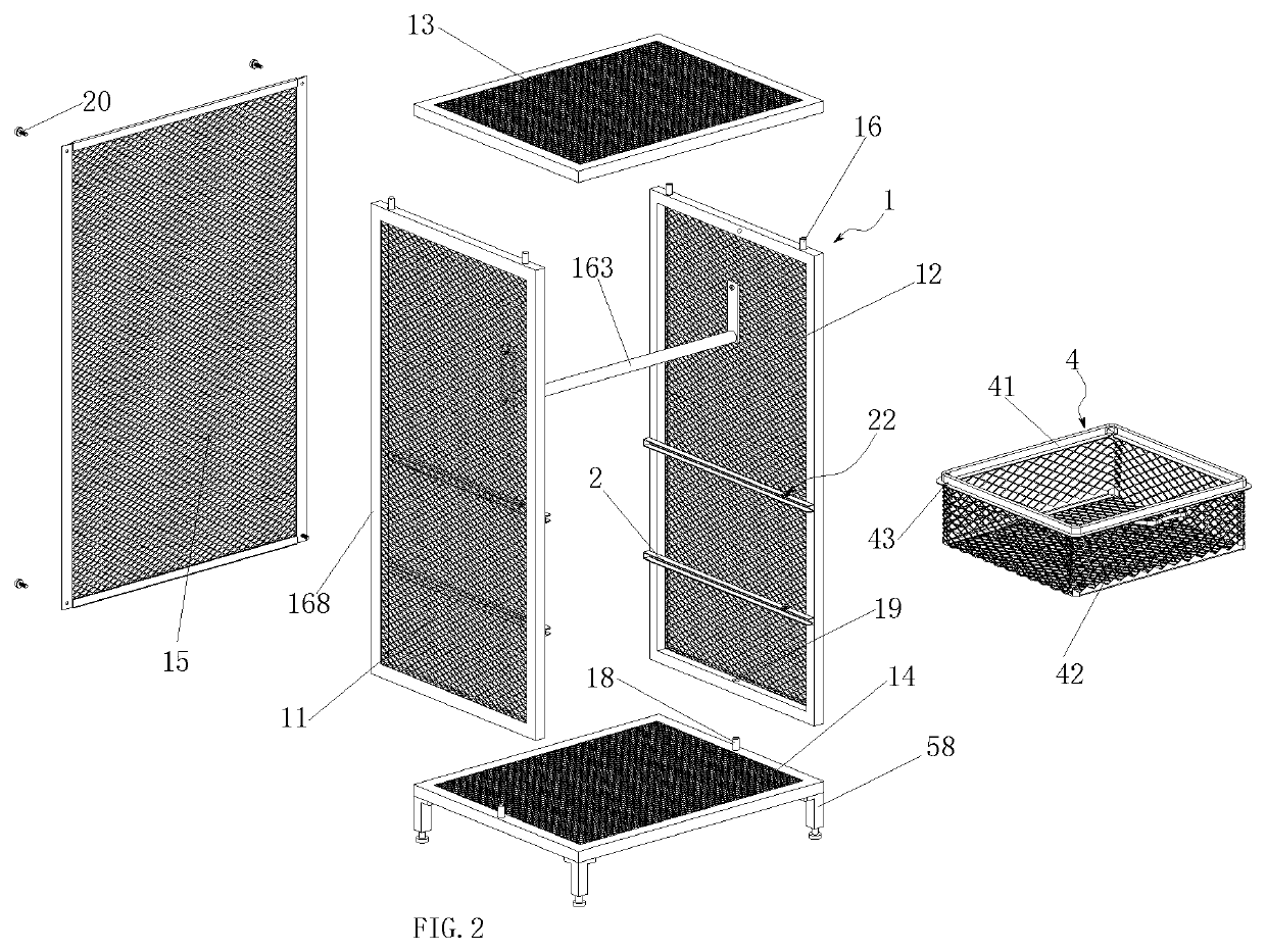
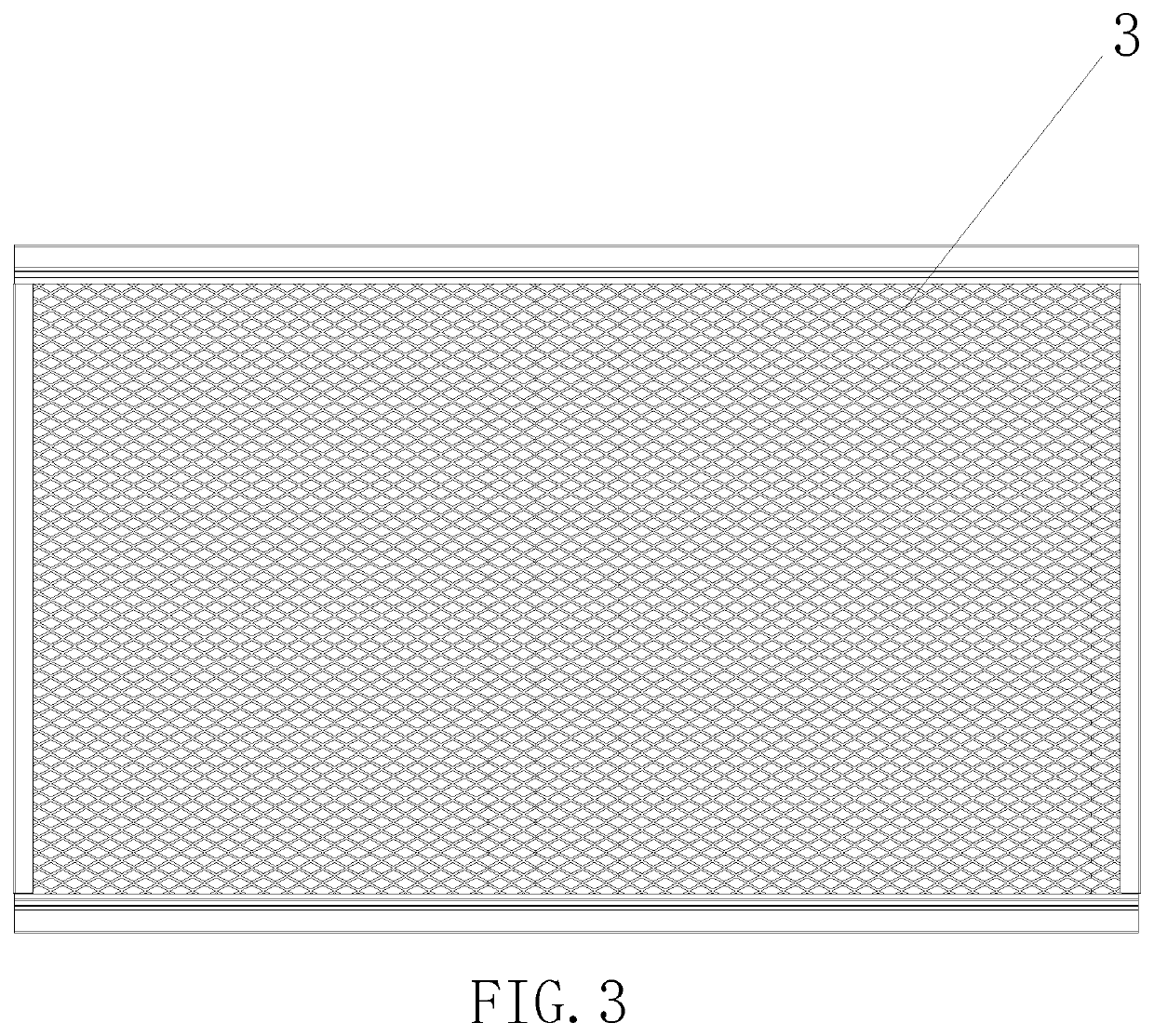
[0041]Referring to FIGS. 1 to 19, a multifunctional breathable storage cabinet according to an embodiment of the utility model includes a frame body 1, the frame body 1 includes a left frame 11 and a right frame 12, and at least one set of sliding rails 2 is corresponding mounted on the left frame 11 and the right frame 12; a storage basket 4 capable of sliding along the sliding rail 2 is mounted on the sliding rail 2; one inward end of the sliding rail 2 is provided with a baffle 21, and the inner wall of one outward end of the sliding rail 2 is provided with an elastic limiting device 22; the storage basket 4 includes a sliding connecting piece 41 capable of being inserted in the sliding rail 2 and sliding along the sliding rail 2 and a metal mesh storage basket body 42 connected with the sliding connecting piece 41, and the sliding connecting piece 41 is provided with a limiting protrusion 43 capable of being in contact with the elastic limiting device 22 to limit the storage bas...
embodiment 2
[0057]Embodiment 2 differs from Embodiment 1 in that the structure of the frame body 1 is different, and other structures thereof are the same as those of Embodiment 1, which will not be repeated herein. As shown in FIGS. 20 and 21, in the embodiment, the frame body 1 further includes an upper frame 13, a lower frame 14 and a rear frame 15; the left frame 11 is formed by inserting a first left frame unit 111 and a second left frame unit 112, and the right frame 12 is formed by inserting a first right frame unit 121 and a second right frame unit 122; the first left frame unit 111, the upper frame 13 and the first right frame unit 121 are integrally bent into an inverse U shape through a metal mesh; the second left frame unit 112, the lower frame 14 and the second right frame unit 122 are integrally bent into a U shape through a metal mesh; the bottoms of the first left frame unit 111 and the first right frame unit 121 are respectively provided with at least one third connecting piece...
embodiment 3
[0060]Embodiment 3 differs from Embodiment 1 in that the structure of the frame body 1 is different, and other structures thereof are the same as those of Embodiment 1, which will not be repeated herein. As shown in FIGS. 22 and 23, in the embodiment, the frame body 1 further includes an upper frame 13 and a rear frame 15; the tops of the left frame 11 and the right frame 12 are respectively provided with at least one first connecting piece 16, the bottom of the upper frame 13 is provided with a first opening 17 adapted to the first connecting piece 16, and the first connecting piece 16 is inserted in the first opening 17 to connect the left frame 11 and the right frame 12 with the upper frame 13; connecting rod assemblies 32 capable of folding the left frame 11 and the right frame 12 are mounted on the lower portions of the left frame 11 and the right frame 12, and the rear frame 15 is connected with the rear of the left frame 11 and the rear of the right frame 12 through fasteners...
PUM
 Abstract
Description
Claims
Application Information
 - R&D
- Intellectual Property
- Life Sciences
- Materials
- Tech Scout
- Unparalleled Data Quality
- Higher Quality Content
- 60% Fewer Hallucinations
Browse by: Latest US Patents, China's latest patents, Technical Efficacy Thesaurus, Application Domain, Technology Topic, Popular Technical Reports.
© 2025 PatSnap. All rights reserved.Legal|Privacy policy|Modern Slavery Act Transparency Statement|Sitemap|About US| Contact US: help@patsnap.com


