Buffer optimization in modular switches

a modular switch and buffer capacity technology, applied in the field of buffer capacity optimization in modular switches, can solve the problems of high throughput, congestion at the line card, congestion at the head of line, etc., and achieve the effect of reducing system cost, high throughput, and small buffer capacity

Active Publication Date: 2020-05-05
MELLANOX TECHNOLOGIES LTD
View PDF94 Cites 0 Cited by
  • Summary
  • Abstract
  • Description
  • Claims
  • Application Information

AI Technical Summary

Benefits of technology

[0014]Embodiments of the invention provide an optimized packet buffer architecture to provide high throughput through while maintaining a small buffer capacity in ASiCs of the network elements. A small reorder buffer can be economically supported by an embedded memory, which reduces the cost of the system for a given number of ports and bandwidth. Buffer memory requirements are kept small by implementing the reordering domain as hash tables rather than linked lists. Hash collisions can be practically avoided by a suitable choice of hashing function. Compared with known hash-based forwarding schemes, head-of-line congestion is lessened because at any point in time the hash table is mainly populated by packet descriptors having closely related incremental sequence numbers, which facilitates design of a suitable hash function in which collisions are rare.

Problems solved by technology

One of the main challenges in designing modular switches is providing high throughput.
The drawback is that hashing does not spread the traffic ideally among the fabric switches, with the result that congestion occur at the line card, known as head-of-line (HOL) congestion.
Moreover, when the number of flows is low hash performance is particularly weak.

Method used


Image

  • Buffer optimization in modular switches
  • Buffer optimization in modular switches
  • Buffer optimization in modular switches

Examples


first alternate embodiment

[0070]Reference is now made to FIG. 5, which is a detailed block diagram of a portion of the fabric 32, which is operated in accordance with an alternate embodiment of the invention. In this embodiment a bandwidth manager 78 is linked to the spine nodes 34, 36, 38, 40 and leaf nodes 42, 44, 46, 48. The bandwidth manager 78 controls aspects of the operation of the fabric 32, such as routing of messages, performing any necessary arbitration, and remapping of inputs to outputs. Routing issues typically relate to the volume of the traffic and the bandwidth required to carry the traffic, which may include either the aggregate bandwidth or the specific bandwidth required between various pairs of computing nodes (or both aggregate and specific bandwidth requirements). Additionally or alternatively, other characteristics may be based, for example, on the current traffic level, traffic categories, quality of service requirements, and / or on scheduling of computing jobs to be carried out by co...

second alternate embodiment

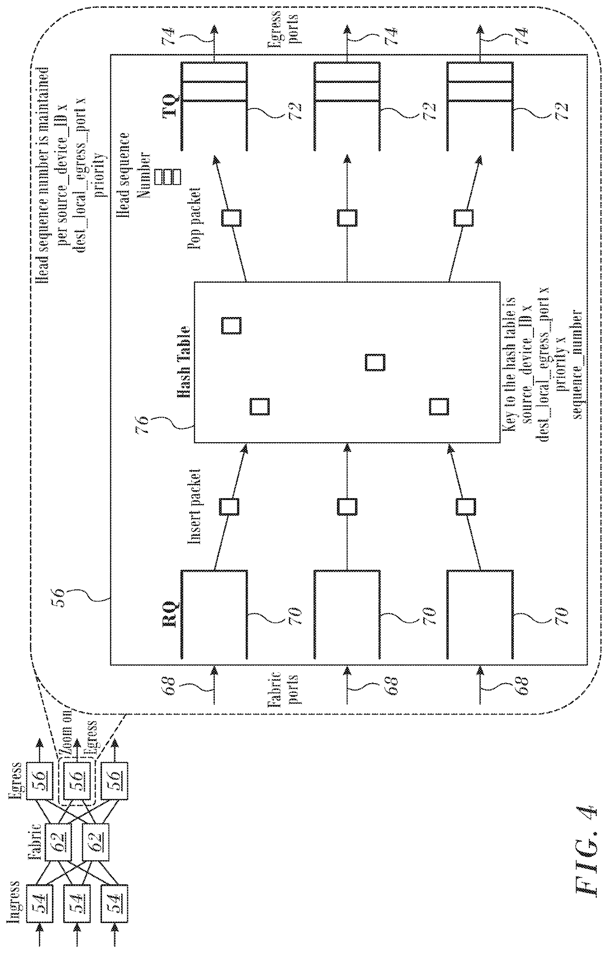
[0074]Reference is now made to FIG. 6, which is a diagram illustrating packet forwarding by egress device 56 in accordance with an alternate embodiment of the invention. This embodiment is similar to FIG. 4, except now the egress devices 56 may maintain multiple instances of a hash table 80 that service one or more of the transmit queues 72 and associated egress ports 74.


PUM


Abstract

In a packet network of ingress nodes and egress nodes connected by a fabric transmit queues are associated with a hash table that stores packet descriptors. When new packets are received in the ingress nodes, credits are obtained from the egress nodes that reflect capacities of the transmit queues to accommodate the new packets. The credits are consumed by transmitting at least a portion of the new packets from the ingress nodes to the egress nodes via the fabric and storing descriptors of the new packets in a hash table. In order to transmit the packets in order by sequence number, when a desired packet sequence number is found by a hash lookup, the new packet having that sequence number is forwarded through the egress nodes.

Description

COPYRIGHT NOTICE[0001]A portion of the disclosure of this patent document contains material that is subject to copyright protection. The copyright owner has no objection to the facsimile reproduction by anyone of the patent document or the patent disclosure, as it appears in the Patent and Trademark Office patent file or records, but otherwise reserves all copyright rights whatsoever.BACKGROUND OF THE INVENTION[0002]1. Field of the Invention[0003]This invention relates to transmission of digital information over data networks. More particularly, this invention relates to operations in the routing of packets in data switching networks.[0004]2. Description of the Related Art[0005]The meanings of certain acronyms and abbreviations used herein are given in Table 1.[0006]TABLE 1Acronyms and AbbreviationsASICApplication-Specific Integrated CircuitDSIDDestination Switching IdentifierHOLHead Of the LineRQReceive QueueRTTRound Trip TimeSSIDSource Switching IdentifierTQTransmit QueueVOQVirtua...

Claims


Application Information

Patent Timeline
Patent Type & Authority Patents(United States)
IPC IPC(8): H04L12/879H04L12/801H04L12/937H04L12/26H04L12/935H04L49/901H04L49/111
CPCH04L49/254H04L47/34H04L49/901H04L49/3036H04L43/0864
Inventor ROSEN, AMIRLEVY, GIL
Owner MELLANOX TECHNOLOGIES LTD
Why Eureka
Try Eureka