
Vacuum cleaner nozzle having rotatable brush

a vacuum cleaner and rotatable technology, which is applied in the direction of brushes, suction cleaners, domestic applications, etc., can solve the problems of polluting the rotatable brush, hindering the cleaning ability, and users are unable to see if the rotatable brush is polluted, so as to achieve easy identification of the different power settings, easy cleaning, and less pollution

Active Publication Date: 2020-05-05
VERSUNI HLDG BV
View PDF18 Cites 0 Cited by
  • Summary
  • Abstract
  • Description
  • Claims
  • Application Information

AI Technical Summary

Benefits of technology

The invention is a vacuum cleaner nozzle with a rotating brush that has a light guide system to distribute light from a static LED positioned in the brush. This allows users to monitor the brush's speed of rotation and the state of its pollution. The brush can be cleaned more frequently as pollution is easier to notice, and users can easily identify the different power settings for the brush. The technical effect is an improved user experience in using the vacuum cleaner nozzle with the rotating brush.

Problems solved by technology

Because of this, the user is also unable to see if the rotatable brush is polluted.
The pollution occurs when strands of textile, human or pet hair among other items roll and attach to the rotatable brush core.
Also, these items get inside the tufts (flexible plastic brush hairs) of the rotatable brush and hinder the cleaning ability.
As the user is unable to see this pollution happening, the user continues to use the appliance but with a degraded performance level as pollution is too high or the rotatable brush roll has completely stopped rotating.
Being able to see markings on a drive belt does not yet allow a user to monitor whether the rotatable brush is polluted.

Method used


Image

  • Vacuum cleaner nozzle having rotatable brush

Examples


first embodiment

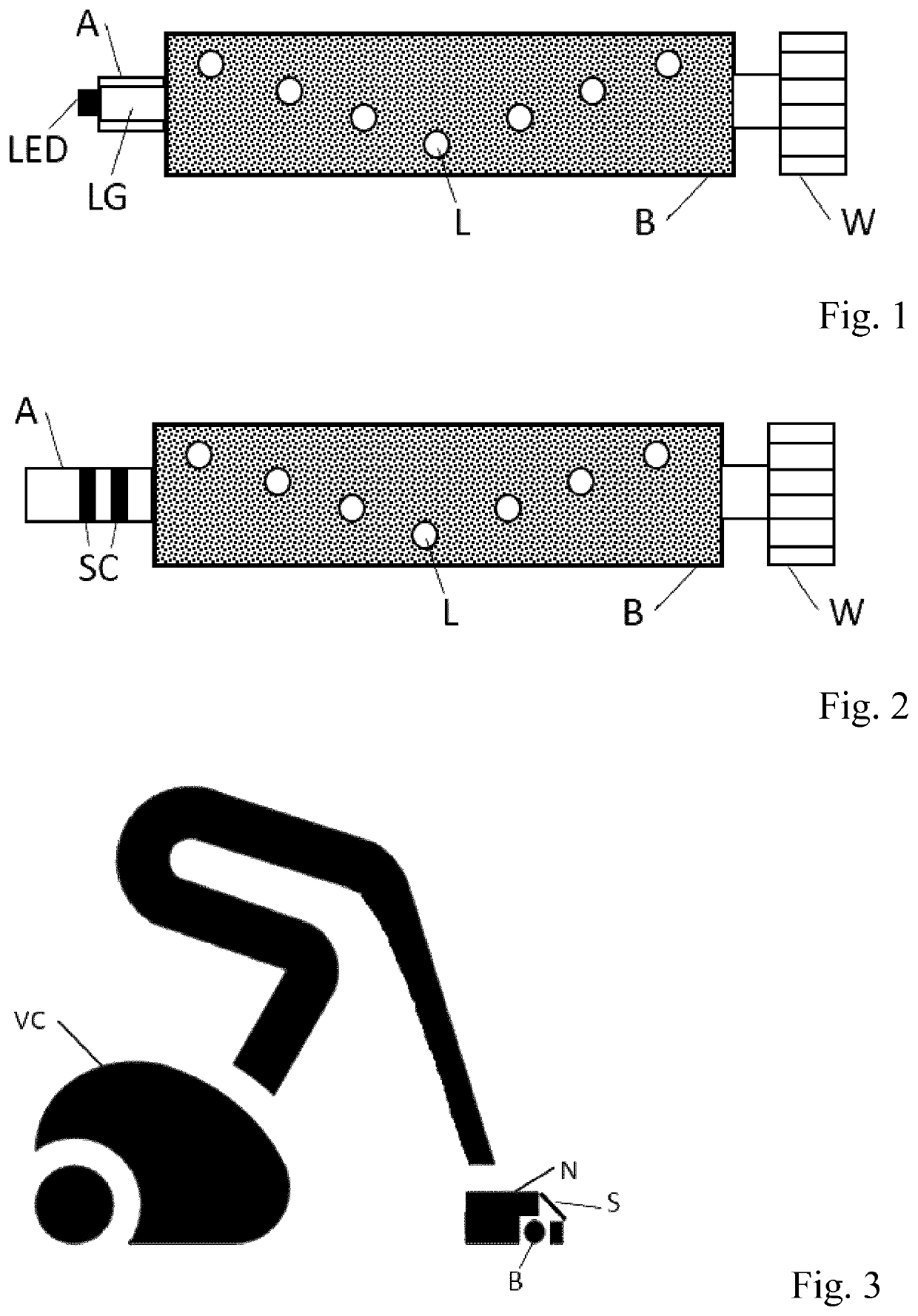
[0013]a rotatable brush for use in a vacuum cleaner nozzle in accordance with the invention is shown in FIG. 1. The rotation around an axis A is caused by a motor which is connected to the rotatable brush B by way of gears or pulley that drive a wheel W. The rotatable brush B has a transparent light conducting material in its core that acts as a light guide LG. Further, the core has radially placed holes or light guides in the core in order to guide the light from the core to the outer part of the rotatable brush roll where it can radiate to the ambience via a plurality of openings L. Further, one or more LEDs are positioned in the vacuum cleaner nozzle in such a place that the LED does not rotate but shines light in axial direction into the transparent core of the rotatable brush B. The LED is therefore positioned in a static part of the vacuum cleaner nozzle, and the LED is thus not vulnerable to high rotation speed or pollution of connection. Also, as the LED is in a static part,...

second embodiment

[0021]FIG. 2 shows a rotatable brush for use in a vacuum cleaner nozzle in accordance with the invention. This embodiment differs from that of FIG. 1 in that the axis A is provided with sliding contacts SC by means of which electrical energy can be transmitted to the rotatable brush B. In this way, it is possible to power an LED in the rotatable brush B that applies light to a light guide from which light escapes at the plurality of openings L. Alternatively, at each of these openings L a separate LED is provided.

[0022]FIG. 3 shows an embodiment of a vacuum cleaner VC comprising a vacuum cleaner nozzle N having a rotatable brush B in accordance with the invention. The vacuum cleaner nozzle N has a transparent screen S through which a user can see the rotatable brush B. If the rotatable brush B rotates, the user will see the rotating lights from the rotatable brush B through the screen S. The vacuum cleaner nozzle N comprises a drive unit to make the rotatable brush B rotate. The dri...


PUM


Abstract

A vacuum cleaner nozzle (N) comprising a rotatable brush (B) having a light distribution mechanism for distributing light from the rotatable brush (B), a transparent screen (S) through which a user can see the rotatable brush (B), and a drive unit for rotating the rotatable brush (B). The light distribution mechanism may have a plurality of lighting positions (L) on the rotatable brush (B). The light distribution mechanism may have a plurality of light sources distributed over a surface of the rotatable brush (B). The light distribution mechanism may have a light guide (LG) inside the rotatable brush (B), from which light escapes at the plurality of lighting positions (L), and may further have a light source (LED) for applying light to the light guide (LG). Alternatively, the light distribution mechanism has a plurality of mirrors at the lighting positions (L). The vacuum cleaner nozzle (N) may further have a sensor for measuring a rotation speed of the rotatable brush (B), and a controller for controlling the light distributed from the rotatable brush (B) in dependence on the rotation speed. The vacuum cleaner nozzle (N) can be applied in a vacuum cleaner further having a dirt collecting unit for collecting dirt.

Description

[0001]This application is the U.S. National Phase application under 35 U.S.C. § 371 of International Application No. PCT / EP2018 / 053436, filed on Feb. 12, 2018, which claims the benefit of International Application No. 17156931.2, filed Feb. 20, 2017. These applications are hereby incorporated by reference herein.FIELD OF THE INVENTION[0002]The invention relates to a vacuum cleaner nozzle having a rotatable brush, and to a vacuum cleaner provided with the vacuum cleaner nozzle.BACKGROUND OF THE INVENTION[0003]U.S. Pat. No. 6,289,552 discloses a vacuum cleaner including a housing having a nozzle that incorporates an agitator cavity. A rotary agitator is received in the agitator cavity. A light source is held in an illumination compartment carried on the housing. A first window divides the illumination compartment from the agitator cavity and a second window provides an outer facing for the illumination compartment. The light source illuminates the agitator which is viewed through the ...

Claims


Application Information

Patent Timeline
Patent Type & Authority Patents(United States)
IPC IPC(8): A47L9/28A47L9/30A46B15/00A47L9/04
CPCA46B15/0036A47L9/2831A47L9/2836A47L9/30A47L9/0477A46B13/001A47L9/2805A47L9/2847A46B2200/3033A46B15/0077
Inventor KLEINE-DOEPKE, BASTIAN CORNELISVAN DER WAL, PAUL
Owner VERSUNI HLDG BV
Learn More