
Image capturing module having multiple lenses

a technology of image capturing and lens module, which is applied in the field of image capturing modules, can solve the problems of quality loss, blurry images, and inability to capture images, and achieve the effects of reducing magnetic interference, reducing quality loss, and reducing quality loss

Active Publication Date: 2020-04-28
POWERGATE OPTICAL INC
View PDF14 Cites 1 Cited by
  • Summary
  • Abstract
  • Description
  • Claims
  • Application Information

AI Technical Summary

Benefits of technology

This configuration effectively reduces magnetic interference, maintains high horizontal driving forces, and ensures precise image capture even at close lens module distances, enhancing the integrated image quality and stability.

Problems solved by technology

However, when using the lens module of smart phone to take photos, minor shakings of smart phone will make the lens tilts, causing the observation angle of lens module varies, resulting in the imaging position on the image sensor to offset from its original position, and thus causing the captured image to blur.
Blurry images definitely are deficiencies and quality losses for combined images of two lens modules.
Traditional design of auto-focusing (AF) and / or optical image stabilization (OIS) lens modules has very poor ability to prevent the magnetic interference, therefore, the two lens modules must be displaced from each other for a significant distance to provide normal functions, and thus is inadequate to suit the needs of design for novel smart phones.

Method used


Image

  • Image capturing module having multiple lenses
  • Image capturing module having multiple lenses
  • Image capturing module having multiple lenses

Examples


first embodiment

[0108]Please refer to FIG. 6B, which is a diagram showing a test result of the offset of optical axis influenced by the magnetic interference caused by the driving magnets of the dual lens modules of the image capturing module of the present invention shown in FIG. 6A. As shown in FIG. 6A, the first lens module 21 has its two smaller auxiliary driving magnets 218 (i.e., the second and third auxiliary driving magnets 218) positioned at the notch side neighboring the adjacent surface 20, in addition, the second lens module 22 has its larger auxiliary driving magnets 224 (i.e., the first auxiliary driving magnets 224) positioned at the side neighboring the adjacent surface 20. Due to the fact that the sizes and strengths of magnetic fields of these auxiliary driving magnets 218, 224 are much smaller than that of the primary driving magnets 213, 223, it can be seen from FIG. 6B that, the offset value of optical axis is still kept at a very small value near to zero when the spacing betwe...

third embodiment

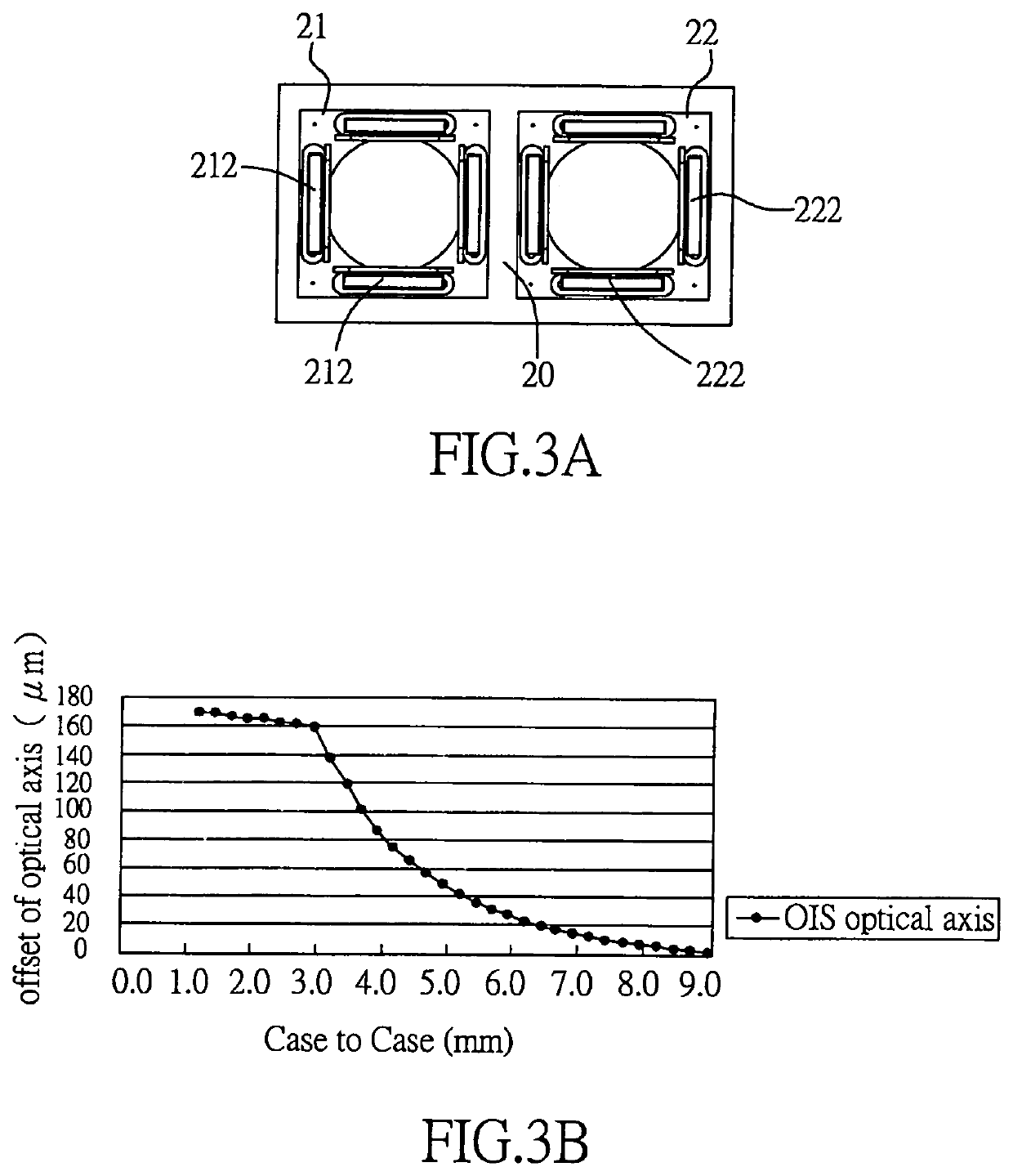
[0111]FIG. 7C is a schematic view of the horizontal circuits formed on the circuit board of the first lens module of the image capturing module having multiple lenses in accordance with the present invention. The two X-axis coils 216x co-work with the first auxiliary driving magnet and the second auxiliary driving magnet to generate horizontal driving forces along the X-axis. As shown in FIG. 7C, the X-axial position sensor 218x is located under the third auxiliary driving magnet for avoiding magnetic interference. There is no X-axis coil at the location above the X-axial position sensor 218x. The third auxiliary driving magnet not only can avoid or minimize the magnetic interference, but also can co-work with the X-axial position sensor 218x for providing closed-loop control function. The X-axis coil 216x below the first auxiliary driving magnet will have sufficient length, size and space for providing adequate horizontal driving force along the X-axis direction. The existence of t...

second embodiment

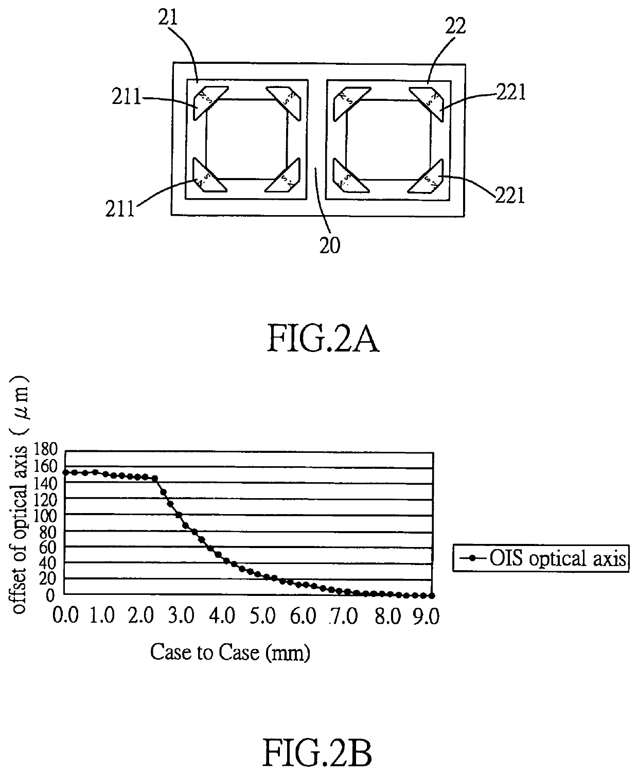
[0154]FIG. 21 is a diagram showing a test result of the offset of optical axis influenced by the magnetic interference caused by the driving magnets of the dual lens modules of the image capturing module of the twenty-second embodiment of the present invention shown in FIG. 19. It can be seen from FIG. 21 that, according to the concept of summed magnetic fields, the offset value of the optical axis is as low as 22 μm even when the spacing between the outer cases of the first and second lens modules 21,22 is 1 mm, it is due to the configuration that, one side of the adjacent surface 20 is furnished with the shorter second and third auxiliary driving magnets 218 of first lens module 21, while the other side of the adjacent surface 20 is furnished with the shorter second auxiliary driving magnet 228 of first lens module 22, and these auxiliary driving magnets 218, 228 are arranged in a staggered order.

[0155]Based on the configuration of the image capturing module having multiple lenses...


PUM


Abstract

An image capturing module having multiple lenses, in which primary driving magnets of auto-focus module equipped in a first lens module and a second lens module will not cover an adjacent surface located between these two lens modules in the same time. A relatively smaller magnet is used to be the auxiliary driving magnet of optical image stabilization (OIS) module equipped in the first lens module and the second lens module. By using the aforementioned configuration of the primary and auxiliary driving magnets, interference of magnetic fields is minimized, and thus the distance between the first and second lens modules can be decreased, and the space of mobile phone having the image capturing module is saved. Moreover, such configuration can be used on the image capturing module having many lens modules.

Description

BACKGROUND OF INVENTION1. Field of the Invention[0001]The invention refers to an image capturing module, and more particularly to an image capturing module having multiple lenses, tri-axial close-loop control and optical image stabilization system.2. Description of the Prior Art[0002]High quality image is one of the important concerns when choosing a smart phone or tablet with camera function. Smart phone with dual lens modules can provide better image capturing results. The difference between the images captured by these two lens modules must be as tiny as possible such that the system can overlay the images precisely; therefore, the two lens modules must be located as near as possible, in order to obtain the best result of integrated image. Of course, when combining two images captured by two lens modules, better result in depth of field can also be acquired, so as to capture fast-moving objects in a more stabilized manner. However, when using the lens module of smart phone to tak...

Claims


Application Information

Patent Timeline
Patent Type & Authority Patents(United States)
IPC IPC(8): H04N5/232G02B27/64H04N13/239G02B9/04G02B7/09G02B7/10G02B13/00H04N5/225
CPCG02B27/646H04N13/239H04N5/23287G02B9/04H04N5/23212G02B13/003H04N5/2257H04N5/23248G02B7/09G02B7/102H04N23/45H04N23/50H04N23/57H04N23/55H04N23/687H04N23/68H04N23/67
Inventor HUANG, YING CHUNCHEN, YU CHIACHUANG, HSIEH JENHO, TE PAOWEN, SHIH CHAN
Owner POWERGATE OPTICAL INC
Learn More