Heat pump with interleaved evaporator/condenser arrangement

a technology of interleaved evaporators and condensers, which is applied in heat pumps, refrigerating machines, lighting and heating apparatus, etc., can solve the problems of unproblematic uncritical reduction of the thickness of the condenser space, and loss of apparatus in the heat exchanger. , to achieve the effect of high-efficiency condensation of vapor

Active Publication Date: 2020-04-28
EFFICIENT ENERGY GMBH
View PDF16 Cites 0 Cited by
  • Summary
  • Abstract
  • Description
  • Claims
  • Application Information

AI Technical Summary

Benefits of technology

[0022]This arrangement, which is mutually “interleaved” in that the evaporator is almost entirely or even entirely arranged within the condenser, enables very efficient implementation of the heat pump with optimum space utilization. Since the condenser space extends right up to the evaporator base, the condenser space is configured within the entire “height” of the heat pump or at least within a major portion of the heat pump. At the same time, however, the evaporator space is as large as possible since it also extends almost over the entire height of the heat pump. Due to the mutually interleaved arrangement in contrast to an arrangement where the evaporator is arranged below the condenser, the space is exploited in an optimum manner. This enables particularly efficient operation of the heat pump, on the one hand, and a particularly space-saving and compact design, on the other hand, since both the evaporator and the condenser extend over the entire height. Thus, admittedly, the levels of “thickness” of the evaporator space and of the condenser space decrease. However, one has found that the reduction of the “thickness” of the evaporator space, which tapers within the condenser, is unproblematic since the major part of the evaporation takes place in the lower region, where the evaporator space fills up almost the entire volume available. On the other hand, the reduction of the thickness of the condenser space is uncritical particularly in the lower region, i.e., where the evaporator space fills up almost the entire region available since the major part of the condensation takes place at the top, i.e., where the evaporator space is already relatively thin and thus leaves sufficient space for the condenser space. The mutually interleaved arrangement is thus ideal in that each functional space is provided with the large volume where said functional space may use said large volume. The evaporator space has the large volume at the bottom, whereas the condenser space has the large volume at the top. Nevertheless, that corresponding small volume which for the respective functional space remains where the other functional space has the large volume contributes to an increase in efficiency as compared to a heat pump where the two functional elements are arranged one above the other, as is the case, e.g., in WO 2014072239 A1.
[0023]In embodiments, the compressor is arranged on the upper side of the condenser space such that the compressed vapor is redirected by the compressor, on the one hand, and is simultaneously fed into a marginal gap of the condenser space. Thus, condensation with a particularly high level of efficiency is achieved since a cross-flow direction of the vapor in relation to a condensation liquid flowing downward is achieved. This condensation comprising cross-flow is effective particularly in the upper region, where the evaporator space is large, and does not involve a particularly large region in the lower region where the condenser space is small to the benefit of the evaporator space, in order to nevertheless allow condensation of vapor particles that have reached said region.
[0024]An evaporator base connected to the condenser base is configured such that it accommodates within it the condenser intake and drain, on the one hand, and the evaporator intake and drain, it being possible, additionally, for certain passages for sensors to be present within the evaporator and / or within the condenser. In this manner, one achieves that no passages of conduits through the evaporator may be used for the capacitor intake and drain, which is almost under a vacuum. As a result, the entire heat pump becomes less prone to defects since each passage through the evaporator would present a possibility of a leak. To this end, the condenser base is provided with a respective recess in those positions where the condenser intakes and drains are located, to the effect that no condenser feed inlets / discharge outlets extend within the evaporator space defined by the condenser base.
[0026]In specific implementations, the evaporator base is configured to comprise connection pipes for the individual feed inlets, which have cross-sections differing from a cross-section of the opening on the other side of the evaporator base. The shape of the individual connection pipes is then configured such that the shape, or cross-sectional shape, changes across the length of the connection pipe, but the pipe diameter, which plays a part in the flow rate, is almost identical with a tolerance of ±10%. In this manner, water flowing through the connection pipe is prevented from starting to cavitate. Thus, on account of the good flow conditions obtained by the shaping of the connection pipes, it is ensured that the corresponding pipes / conduits can be made to be as short as possible, which in turn contributes to a compact design of the entire heat pump.
[0027]In a specific implementation of the evaporator base, the condenser intake is split up into a two-part or multi-part stream, almost in the shape of “eyeglasses”. Thus, it is possible to feed in the condenser liquid in the condenser at its upper portion at two or more locations at the same time. Thus, a strong and, at the same time, particularly even condenser flow from top to bottom is achieved which enables achieving highly efficient condensation of the vapor which is introduced into the condenser from the top as well.
[0029]The evaporator base is characterized in that it exhibits a combination functionality. On the one hand, it is ensures that no condenser feed inlets need to be passed through the evaporator, which is under very low pressure. On the other hand, it represents an interface toward the outside, which may have a circular shape since in the case of a circular shape, a maximum amount of evaporator surface area remains. All of the feed inlets / discharge outlets lead through the one evaporator base and from there extend either into the evaporator space or into the condenser space. It is particularly advantageous to manufacture the evaporator base from plastics injection molding since the advantageous, relatively complicated shapes of the intake / drain pipes can be readily implemented in plastics injection molding at low cost. On the other hand, it is readily possible, due to the implementation of the evaporator base as an easily accessible workpiece, to manufacture the evaporator base with sufficient structural stability so that it can readily withstand in particular the low evaporator pressure.

Problems solved by technology

In this context one has to take into account, however, that this heat exchanger again represents losses and expenditure in terms of apparatus.
However, one has found that the reduction of the “thickness” of the evaporator space, which tapers within the condenser, is unproblematic since the major part of the evaporation takes place in the lower region, where the evaporator space fills up almost the entire volume available.
On the other hand, the reduction of the thickness of the condenser space is uncritical particularly in the lower region, i.e., where the evaporator space fills up almost the entire region available since the major part of the condensation takes place at the top, i.e., where the evaporator space is already relatively thin and thus leaves sufficient space for the condenser space.
As a result, the entire heat pump becomes less prone to defects since each passage through the evaporator would present a possibility of a leak.

Method used


Image

  • Heat pump with interleaved evaporator/condenser arrangement
  • Heat pump with interleaved evaporator/condenser arrangement
  • Heat pump with interleaved evaporator/condenser arrangement

Examples


Embodiment Construction

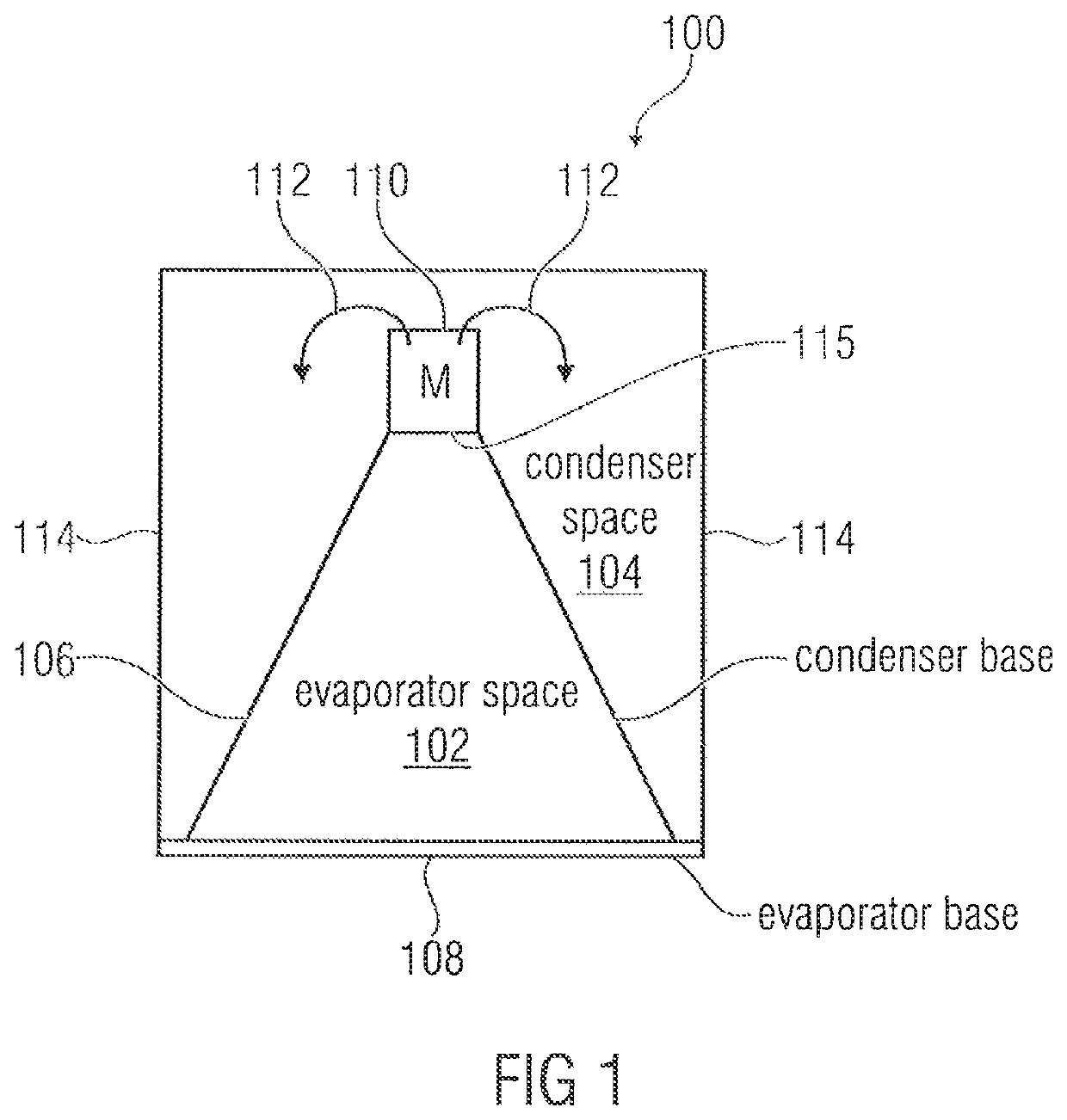
[0047]FIG. 1 shows a heat pump 100 comprising an evaporator for evaporating working liquid within an evaporator space 102. The heat pump further includes a condenser for condensing evaporated working liquid within a condenser space 104 bounded by a condenser base 106. As shown in FIG. 1, which can be regarded both as a sectional representation and as a side view, the evaporator space 102 is at least partially surrounded by the condenser space 104. Moreover, the evaporator space 102 is separated from the condenser space 104 by the condenser base 106. In addition, the condenser base is connected to an evaporator base 108 so as to define the evaporator space 102. In one implementation, a compressor 110 is provided above the evaporator space 102 or at a different location, said compressor 110 not being explained in detail in FIG. 1 but being configured, in principle, to compress evaporated working liquid and to direct same into the condenser space 104 as compressed vapor 112. Moreover, ...


PUM


Abstract

A heat pump includes an evaporator for evaporating working liquid within an evaporator space bounded by an evaporator base, and a condenser for condensing evaporated working liquid within a condenser space bounded by a condenser base, the evaporator space being at least partially surrounded by the condenser space, the evaporator space being separated from the condenser space by the condenser base, and the condenser base being connected to the evaporator base.

Description

CROSS-REFERENCE TO RELATED APPLICATION[0001]This application is a continuation of copending International Application No. PCT / EP2016 / 062060, filed May 27, 2016, which is incorporated herein by reference in its entirety, and additionally claims priority from German Application No. 102015209848.6, filed May 28, 2015, which is incorporated herein by reference in its entirety.[0002]The present invention relates to heat pumps for heating, cooling or for any other application of a heat pump or to an evaporator base for such a heat pump.BACKGROUND OF THE INVENTION[0003]FIG. 8A and FIG. 8B provide a heat pump as is described in European Patent EP 2016349 B1. FIG. 8A shows a heat pump initially comprising a water evaporator 10 for evaporating water as a working liquid so as to generate vapor within a working vapor pipe 12 on the output side. The evaporator includes an evaporation space (evaporation chamber) (not shown in FIG. 8A) and is configured to generate an evaporation pressure smaller ...

Claims


Application Information

Patent Timeline
Patent Type & Authority Patents(United States)
IPC IPC(8): F25B30/02F25B39/02F25B39/00F25B39/04F25B25/00
CPCF25B39/02F25B39/04F25B30/02F25B39/00F25B25/005F25B2500/01F25B2500/18F25B2339/047
Inventor KNIFFLER, OLIVERSEDLAK, HOLGER
Owner EFFICIENT ENERGY GMBH
Why Eureka
Try Eureka