
Wireless sensor system for a vehicle

a sensor system and vehicle technology, applied in the field of wireless sensor systems, can solve the problems of limiting the locations where such non-wired sensors can be installed upon and/or within the vehicle, unable to reliably communicate in real-time over long distances at a sufficient data transfer rate, and achieving the effect of low profil

Active Publication Date: 2020-04-21
DEFENCE INNOVATIONS IP PTY LTD
View PDF6 Cites 14 Cited by
  • Summary
  • Abstract
  • Description
  • Claims
  • Application Information

AI Technical Summary

Benefits of technology

This patent describes a system that allows for a gateway device to control and communicate with sensor nodes on a vehicle. The gateway can store sensor data and transmit it either continuously or in batches. There is also an accurate time keeping system to ensure that all recorded events and information are properly tied to a specific time. Additionally, the system includes a remote user interface that allows for easy management of the sensor system by either a person inside or outside of the vehicle. The patent also describes a fastening system that allows for easy attachment and removal of sensor nodes without damaging the surface or needing special tools. Overall, the patent expands the capabilities of vehicle sensor systems and allows for better data management and analysis.

Problems solved by technology

One problem associated with current sensing systems for high performance vehicles is that current commercially available non-wired sensors are large and bulky.
This severely limits the locations where such non-wired sensors can be installed upon and / or within the vehicle.
Another major problem with wireless sensors is that none of the commercially available ones can reliably communicate in real-time over long distances at a sufficient data transfer rate.
The more extreme the operational parameters of the vehicle become, such as speed, component stress, altitude and the like, so too does the problem of being able to send and receive real-time data transmissions.
The problem is exacerbated when the number of sensors fitted to the vehicle is increased.
However, on certain types of vehicles, such as aircraft for example, the fitting of wired sensors can take weeks, or even months to install and commission.
This adds significantly to the cost, both direct and indirect, related to having such a high value asset out of commission during the fitting and commissioning phases.
Because of their bulk, the existing types of wireless sensors for use on aircraft can only be installed at limited interior structural locations of the aircraft.
The same problem thereby arises.
There is a substantial direct and indirect cost associated with having an expensive asset, such as an aircraft, out of commission for an extended period of time.
Further to this, no existing sensor system that is currently available can be directly mounted onto coated external aircraft surfaces, and subsequently removed, without damage to the aircraft coating.
Removal of the original coatings to enable sensor installation, and the subsequent repair required, also add significant time and cost.
Strain gauge sensors are typically very fragile and therefore require specialised technicians to install.
Traditional wired sensors may be smaller than their non-wired counterparts, but when wired sensors have the advantage with size, they have the disadvantage of adding the weight of the associated wiring that is required for them to operate.
Air-worthiness certification is both time consuming and very costly.
Also, modified aircraft often become “orphan aircraft” because of their unique modified structures and require individualised maintenance and sustainment plans which are costly and inefficient, thereby making them a burden on aircraft maintenance resources and scheduling.
All this substantially increases the cost and time associated with acquiring real time flight performance data, both in direct costs, and in the ancillary costs surrounding specialised maintenance and recertification.
As modern aircraft, particularly high performance aircraft and aerospace vehicles, continue to become significantly more expensive, many national defence budgets are unable to afford the significant costs associated with new generations of dedicated test aircraft.
Orange wired aircraft are significantly more expensive than regular aircraft.
Due to this significant extra cost, both in acquiring and maintaining them, they are often minimally used to preserve their integrity, and to reduce their wear and tear, and to keep the aircraft within its airworthiness lifespan for as long as possible.
The data acquired from the operation of orange wired aircraft may not be truly representative of the operations of the entire regular fleet.
Furthermore, only acquiring data from one particular aircraft means that the amount of data collected is somewhat limited and may have an undesirable impact on any engineering analysis of that data.
Many advanced coatings have either been developed already, or are under development, that provide a high level of RADAR signal absorption, and this coating cannot be either removed or damaged in relation to the installation of, or removal of, any of the sensors and / or its ancillary equipment.
Furthermore, the installation of the sensors and / or its ancillary equipment cannot significantly alter the shape of the aircraft so that its stealth performance is compromised in any way.
However, no existing sensor system that measures a wide multitude of parameters within one single sensor package is currently available commercially for aircraft testing applications.
This contributes to increased bulk, weight, and power requirements.
Moreover, none of the currently available sensor systems are suitable for use on external surfaces of an aircraft during flight.
Because of the complexity involved in system configuration procedures, and the lack of a suitable interface, they cannot be easily reprogrammed, or the measured data quickly analysed in real-time by the flight crew during the flight.
This is particularly the case in single or two seat aircraft that lack a dedicated team of test engineers on-board, solely responsible for the management of the sensor system, and evaluation of the data obtained.

Method used


Image

  • Wireless sensor system for a vehicle
  • Wireless sensor system for a vehicle
  • Wireless sensor system for a vehicle

Examples


Embodiment Construction

[0077]It must be noted that an aircraft has been chosen purely as an example of a suitable type of high performance vehicle. Any type of high performance vehicle is suitable for this invention.

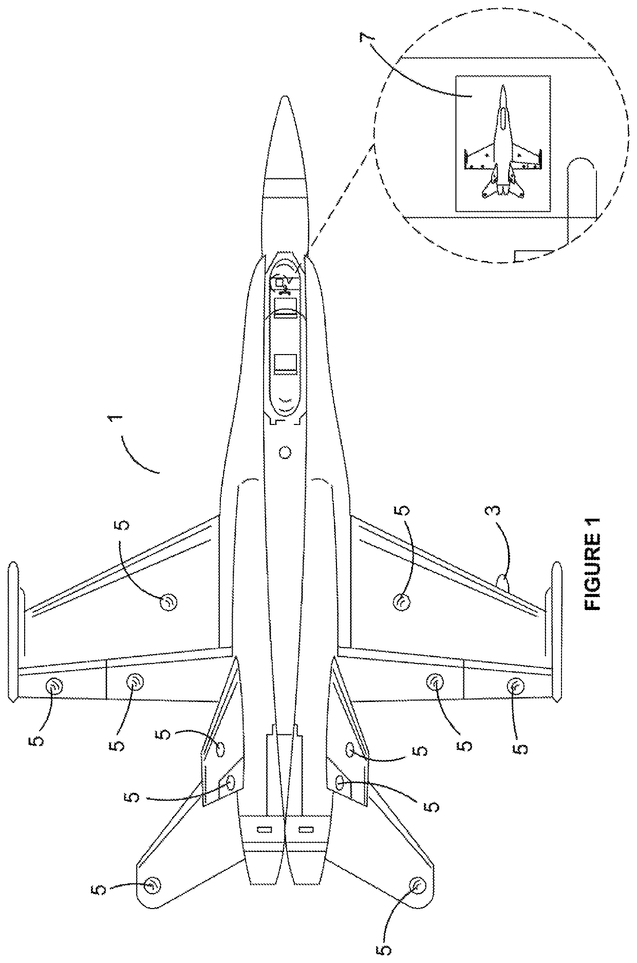
[0078]In FIG. 1, we can see a schematic of the wireless sensor and telemetry system that is the subject of the present invention. to We can see the top view of an aircraft 1 that includes a gateway 3, in this embodiment carried under starboard wing, and a plurality of sensor nodes 5. The gateway 3 and each sensor node 5 is wirelessly connected together for two-way data communication. This two-way communication may be directly between an individual sensor node 5 and the gateway 3, or a cluster of sensor nodes 5 and the gateway 3. In this view we are also shown a cockpit mounted sensor system monitoring and management interface 7.

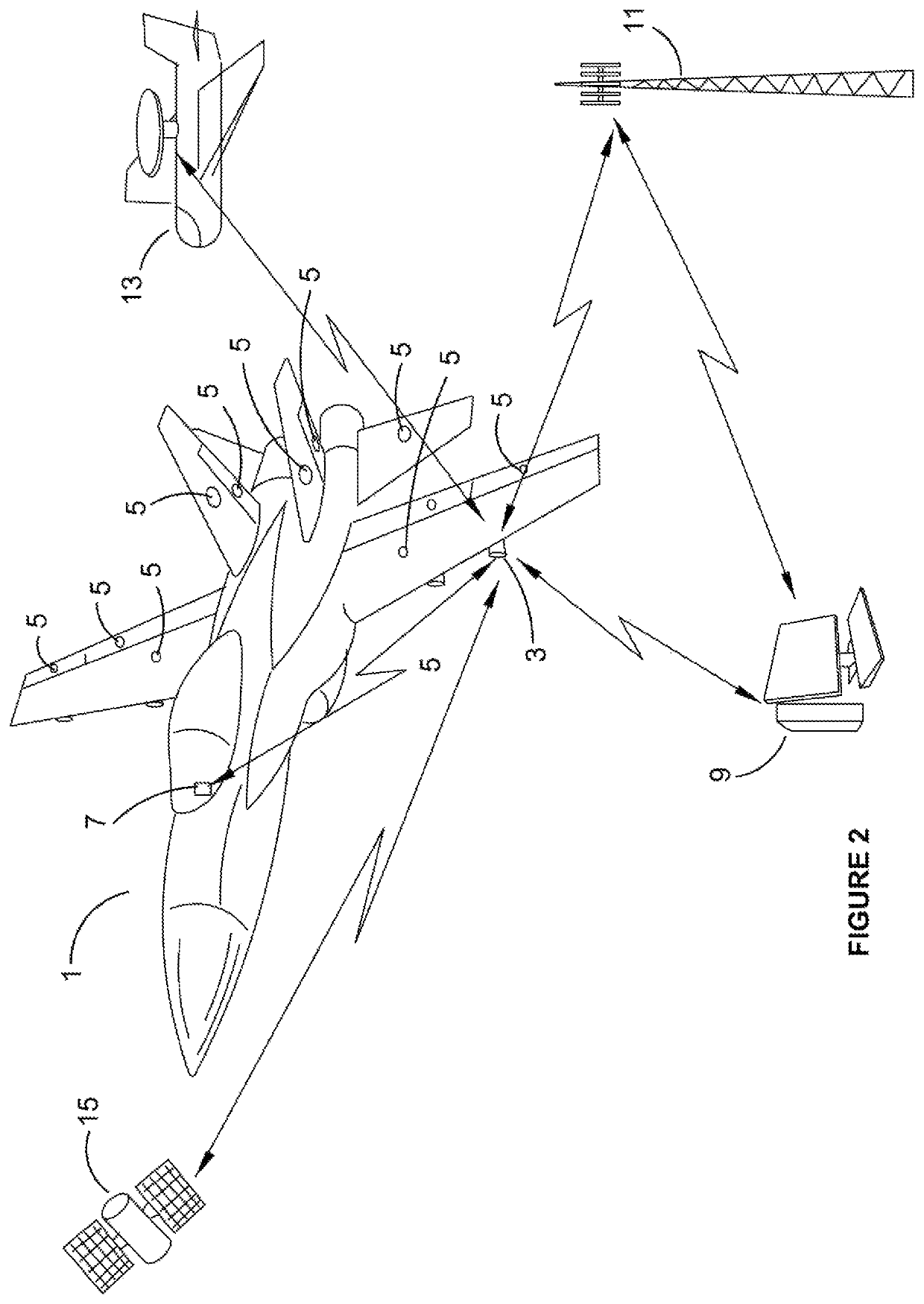
[0079]In FIG. 2 we are shown another schematic of the overall sensor system. The aircraft 1 has a plurality of sensor nodes 5 fitted to strategic positions on the airfr...


PUM


Abstract

The invention is a wireless sensor and telemetry system for use on a vehicle such as an aircraft including at least one sensor node, a gateway, a user control system, data management and analytics means, wherein the sensor node is capable of sensing at least one type of operational performance or structural condition parameter data for the vehicle. Sensor node is attached to the vehicle in a specific location so that the data acquired gives information to the users of the system that relates to the operational performance or structural condition of the vehicle during operation. The sensor node wirelessly transmits the data it acquires to the gateway. The user control system enables person / s, to remotely operate and control the wireless sensor and telemetry system, by sending wireless operational control instructions to the system either via the gateway or directly to a particular sensor node or to a cluster of sensor nodes.

Description

FIELD OF THE INVENTION[0001]This invention relates to a wireless sensor system, for use on high performance vehicles such as aircraft, that includes a plurality of sensor nodes of various types and on-board data collection, storage, transmission, command and control and system integrity checking systems. In particular, the wireless sensor system is able to be self-powered, and attached to, or removed from, the high performance vehicle, with a minimum of vehicle downtime, and without causing any damage to the external surface coating of the vehicle.BACKGROUND OF THE INVENTION[0002]High performance vehicles, for example high performance aircraft and aircraft undergoing testing and research and development, require a reliable, accurate and robust sensor and telemetry system in order to provide real-time operational condition feedback of the measurement data collected by the sensors. This data may be sent as continuous telemetry and / or collected in a central data collection unit for sub...

Claims


Application Information

Patent Timeline
Patent Type & Authority Patents(United States)
IPC IPC(8): G07C5/00H04L29/08B64F5/60B64D45/00G07C5/08H04Q9/00G01S19/13H04W88/16H04W84/18H01Q1/28
CPCG07C5/0816B64F5/60B64D45/00G07C5/008G07C5/0841H04L67/12H04Q9/00H04W88/16G01S19/13B64D2045/0085H01Q1/283H04W84/18
Inventor CANNING, WARREN PETERLOK-KUN HO, DANIELMAHER, AARONZAKOPAYLO, IGORMAHER, DION JAYE
Owner DEFENCE INNOVATIONS IP PTY LTD
Learn More