
Holder for lenses and helmet for such a holder

a technology for eyeglass lenses and helmets, applied in headwear caps, hats, spectales/goggles, etc., can solve the problems of a relatively complex design of holders, and achieve the effect of stable attachment of holders to helmets

Active Publication Date: 2020-04-14
LECHNER STEFAN
View PDF10 Cites 0 Cited by
  • Summary
  • Abstract
  • Description
  • Claims
  • Application Information

AI Technical Summary

Benefits of technology

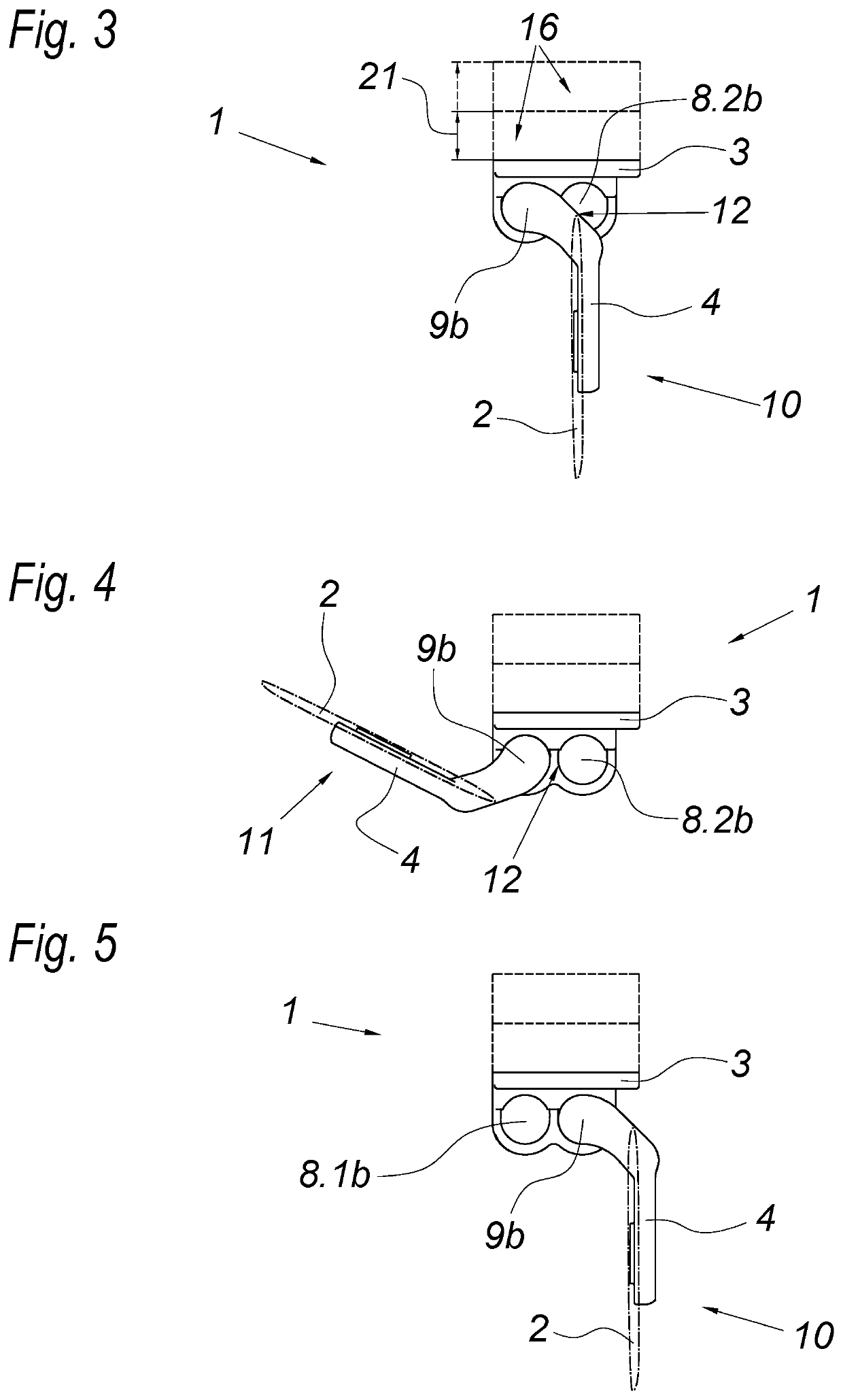
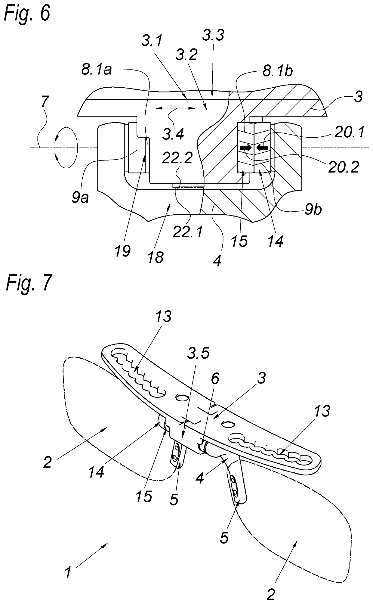
[0005]If the first and second bearing parts are embodied so that they are detachable from each other and stick together magnetically, for which purpose at least one bearing part has at least one permanent magnet with a magnetization direction oriented in the direction of the swivel axis, then this can not only simplify the design of the holding part, but can also free the magnetic holder of swiveling-induced leverage forces, thus making it possible to rule out the occurrence of an unwanted detachment of the magnetic connection when the holding part is swiveled as part of its function. It is thus possible to achieve a particularly stable holder. This simplified design according to the invention, however, does not entail the expectation of a negative effect on use because the holder can be separated relatively easily by overcoming the magnetic forces at the swivel bearing.
[0021]If the fastening part of the holder is fastened to the inner lining of the helmet inside the outer shell, then the small size of the holder can make it possible to provide an unlimited field of view through the eyeglass lenses of the holder. This can also ensure a stable attachment of the holder to the helmet.

Problems solved by technology

Since such a swiveling of the holding part always exerts forces / moments on the magnetic connection between the holding part and the fastening part, a disadvantageous detachment of the holding part from the fastening part must be expected—in order to prevent this, such holders have a comparatively complex design.

Method used


Image

  • Holder for lenses and helmet for such a holder
  • Holder for lenses and helmet for such a holder
  • Holder for lenses and helmet for such a holder

Examples


Embodiment Construction

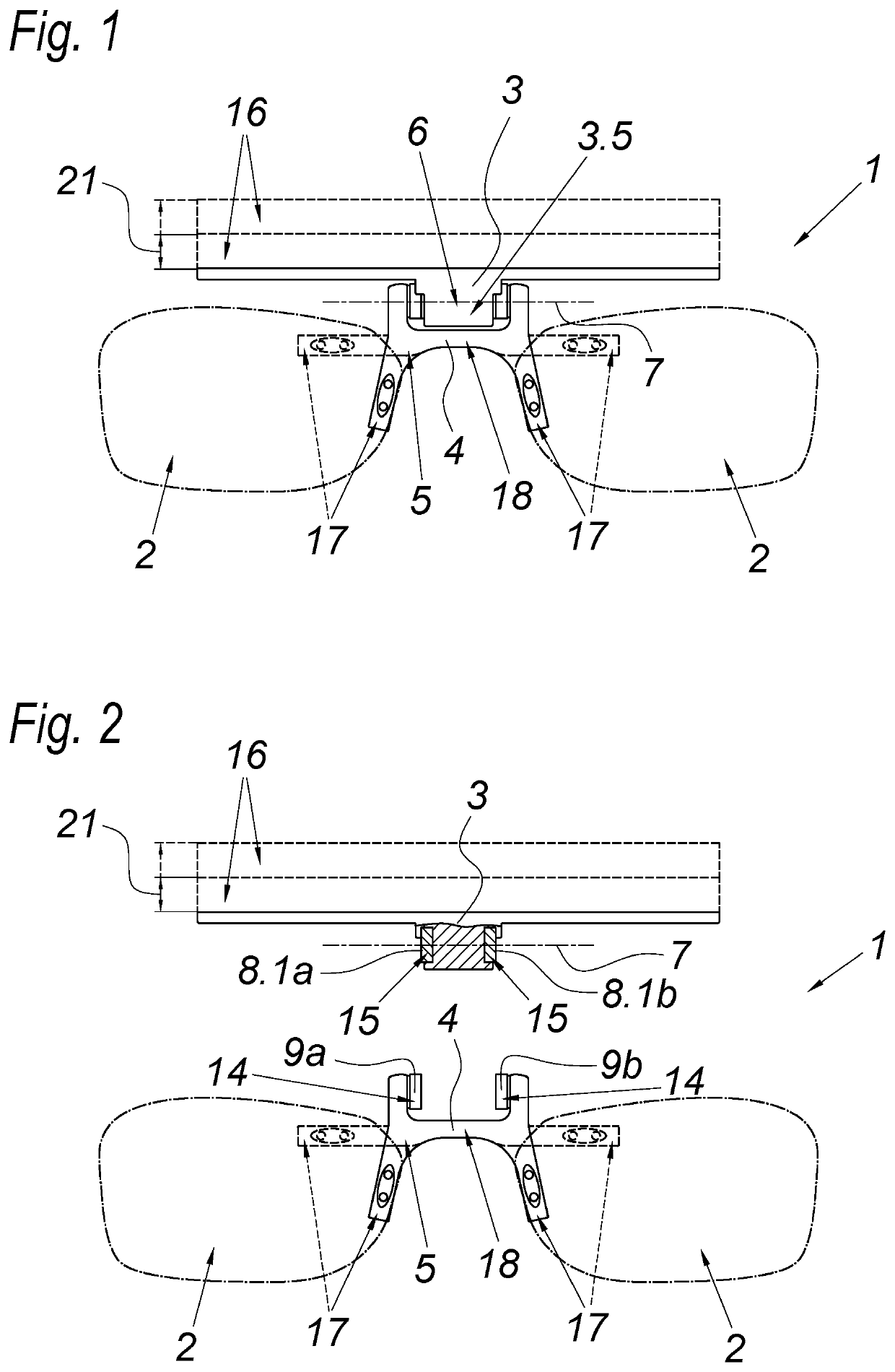
[0030]FIGS. 1 and 2 show a holder 1 for eyeglass lenses 2 in which the holder 1 has a fastening part 3 for attaching the holder 1 to a bead covering, in particular a helmet—but the latter is not shown in the figures. The holder 1 also has a holding part 4, which is magnetically secured to the fastening part 3 in a detachable way.

[0031]FIG. 1 shows an example of a holder 1 in which the holding part 4 is magnetically secured to the fastening part 3. FIG. 2, however, shows a holding part 4 that is detached from the fastening part.

[0032]The holding part 4 in turn has a nose bridge 5 to which the eyeglass lenses 2 are fastened. The nose bridge 5 in this case is embodied so that if at all possible, it does not touch the wearer's nose. Specifically, the holder 1 makes it possible to avoid the nose bridge 5 having to be supported on the wearer's nose—and as a result, no pressure points are produced on the wearer's nose. The nose bridge 5 in this case is divided into two assembly segments 17...


PUM


Abstract

A holder for eyeglass lenses having a holding part, which is magnetically secured to the fastening part in detachable fashion and has a nose bridge for holding eyeglass lenses, and having at least one swivel bearing, which is provided between the fastening part and the nose bridge of the holding part and has at least two bearing parts that are able to swivel relative to each other around the swivel axis of the swivel bearing in order to move the holding part between a use position of the eyeglass lenses and a non-use position of the eyeglass lenses in which they are folded upward in relation to the use position. In order to embody a holder of the above-mentioned type in a reliable and simply designed way, the first bearing parts and second bearing parts are embodied so that they are detachable from each other and are held together magnetically, for which purpose, at least one bearing part has at least one permanent magnet with a magnetization direction oriented in the direction of the swivel axis.

Description

FIELD OF THE INVENTION[0001]The invention relates to a bolder for eyeglass lenses having a fastening part for attaching to a head covering having a holding part, which is magnetically secured to the fastening part in detachable fashion and has a nose bridge for holding eyeglass lenses, and having at least one swivel bearing, which is provided between the fastening part and the nose bridge of the holding part and has at least two bearing parts that are able to swivel relative to each other around the swivel axis of the swivel bearing in order to move the holding part between a use position of the eyeglass lenses and a non-use position of the eyeglass lenses in which they are folded upward in relation to the use position.BACKGROUND OF THE INVENTION[0002]A holder for eyeglass lenses that can be fastened to a helmet is known from the prior art (KR 2012 0116062 A). This holder is essentially composed of a fastening part securely attached to the helmet and a holding part for the eyeglass ...

Claims


Application Information

Patent Timeline
Patent Type & Authority Patents(United States)
IPC IPC(8): G02C3/02A42B1/24A42B3/18
CPCG02C3/02A42B3/185A42B1/247G02C2200/02A42B1/24A47F7/02
Inventor LECHNER, STEFAN
Owner LECHNER STEFAN
Learn More