Fastening device and fastening method of solar cell module

a solar cell module and fastening device technology, applied in the direction of photovoltaic supports, heat collector mounting/supports, light and heating apparatus, etc., can solve the problems of increasing the danger of screw falling or screw falling, complicated installation work while supporting solar cell panels, and increasing the danger of work, so as to sliding, reduce the risk of falling, and reduce the risk of work

Active Publication Date: 2020-03-31
SOLAR FRONTIER
View PDF16 Cites 1 Cited by
  • Summary
  • Abstract
  • Description
  • Claims
  • Application Information

AI Technical Summary

Benefits of technology

[0009]A fastening device which reduces the work by screwing when attaching a solar cell module to a frame and which shortens the installation time has been desired.
[0015]According to the fastening device of the present invention, the second support surface is arranged a constant first interval away from the first support surface of the third module support part when not elastically displaced, while the fourth support surface is arranged a constant second interval smaller than the first interval away from the third support surface of the third module support part when not elastically displaced. Therefore, the second solar cell module biases the third support surface, whereby the first support surface pushes against the first solar cell module and a large frictional force is generated between the first solar cell module and the first support surface and second support surface. Therefore, even if not screwing in the solar cell module, it is possible to suppress shifting and sliding in the horizontal direction. It becomes possible to simplify the work of fastening a solar cell module and thereby possible to shorten the installation time and suppress the danger at the time of installation work.

Problems solved by technology

This installation cost is based on not only the price of the solar cell module itself, but also the installation time of the worker installing the solar cell module on an installation surface.
In the past, to keep down shifting or looseness of solar cell modules, screws have been used to attach the solar cell module to the frame, but screwing work performed on a roof had the danger of falling members or screws.
Installation work while supporting a solar cell panel becomes complicated work.
In the case of work on a home roof, the danger of the work also increases.
The work becomes troublesome.

Method used


Image

  • Fastening device and fastening method of solar cell module
  • Fastening device and fastening method of solar cell module
  • Fastening device and fastening method of solar cell module

Examples


Embodiment Construction

[0035]Below, referring to the attached drawings, embodiments of the present invention will be explained.

[0036]In the following embodiments, the same or similar components are assigned common reference notations. To facilitate understanding, these figures are suitably changed in scale. Further, note that the technical scope of the present invention is not limited to these embodiments and extends to the inventions described in the claims and their equivalents.

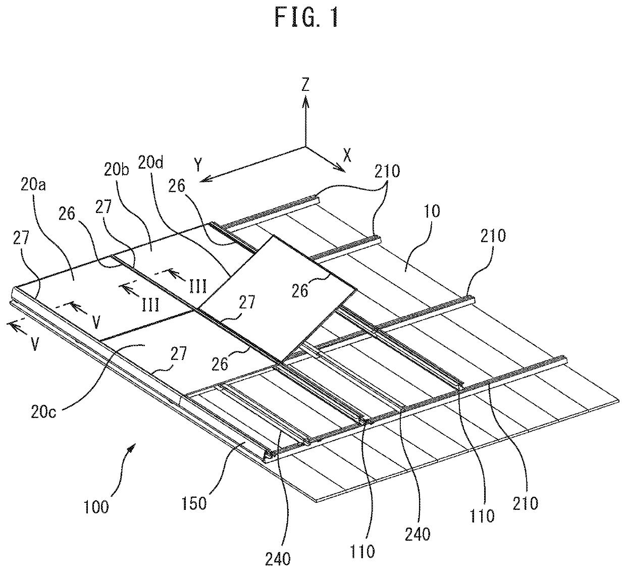
[0037]FIG. 1 is a perspective view which shows a fastening device 100 according to an embodiment of the present invention which fastens solar cell modules 20a to 20d (below, sometimes referred to all together as the “solar cell modules 20”) on an installation surface 10 of a roof. As shown in FIG. 1, a plurality of solar cell modules 20 are successively arranged on the installation surface 10 in the vertical direction and horizontal direction and are fastened by the fastening device 100 to the installation surface 10. In this Des...


PUM


Abstract

A fastening device which reduces the work by screwing and shortens the installation time has been desired. A fastening device 100 which fastens and supports a plurality of solar cell modules 20 includes a base part 111, a first module support part 113 which has a first support surface 113a and which is provided at the base part to be able to elastically displace, a second module support part 114 which has a second support surface 114a and which is provided at the base part, wherein the second support surface is arranged so that the second support surface is away from the first support surface of the first module support part when not elastically displaced at a constant first interval T2, a third module support part 123 which has a third support surface 123a and which is provided at the base part to be able to elastically displace, and a fourth module support part 124 which has a fourth support surface 124a, which fourth module support part is arranged a constant second interval T3 which is smaller than the first interval T2.

Description

CROSS-REFERENCE TO RELATED APPLICATIONS[0001]This application is a national stage application under 35 U.S.C. 371 of International Application No. PCT / JP2014 / 065932, filed Jun. 16, 2014, and which claims priority to Japanese Patent Application No. 2013-151131, filed Jul. 19, 2013, the contents of which are incorporated herein by reference in their entirety.FIELD OF THE INVENTION[0002]The present invention relates to a fastening device which fastens a solar cell module to a roof or other installation surface and a fastening method of a solar cell module which uses the fastening device.BACKGROUND OF THE INVENTION[0003]In recent years, due to interest in the environment and government policies etc., solar cells are increasingly being installed at public facilities, general homes, and all other locations. A solar cell utilizes sunlight, because it is installed outside such as on a roof or a rooftop. To make effective use of the installable surface, a plurality of solar cell modules (als...

Claims


Application Information

Patent Timeline
Patent Type & Authority Patents(United States)
IPC IPC(8): H02S30/10F24S25/35F24S25/65F24S25/20H02S20/23F24S20/00F24S25/00
CPCF24S25/65H02S20/23F24S25/20H02S30/10F24S25/35F24S2025/014F24S2020/11Y02B10/12F24S2025/018Y02E10/47Y02E10/50Y02B10/10
Inventor ITOU, DAISUKEKANBARA, TATSUJI
Owner SOLAR FRONTIER
Why Eureka
Try Eureka