Foot pedal for a trolling motor assembly

a technology of trolling motor and foot pedal, which is applied in the direction of mechanical control devices, instruments, vessel construction, etc., can solve the problem that the electric steering foot pedal assembly does not provide such a resistance for

Active Publication Date: 2020-03-31
NAVICO HLDG
View PDF61 Cites 6 Cited by
  • Summary
  • Abstract
  • Description
  • Claims
  • Application Information

AI Technical Summary

Benefits of technology

[0021]Some existing foot pedals for controlling the operation of trolling motors have buttons attached to a fixed, non-pivotable support plate that communicate with a controller. However, depending on the angle of the foot pedal, in some foot pedal positions, such buttons may be difficult to reach, while in other foot pedal positions, such buttons may subject to accidental actuation. Thus, some embodiments of the present disclosure seek to provide a foot pedal with buttons that are properly accessible independent of the foot pedal position and, in some cases, are disposed on the rotating part of the foot pedal assembly (thereby providing for easy access by a user).

Problems solved by technology

The electronically steered foot pedal assemblies do not provide such as resistance force.

Method used


Image

  • Foot pedal for a trolling motor assembly
  • Foot pedal for a trolling motor assembly
  • Foot pedal for a trolling motor assembly

Examples


Embodiment Construction

[0062]Exemplary embodiments of the present invention now will be described more fully hereinafter with reference to the accompanying drawings, in which some, but not all, embodiments of the invention are shown. Indeed, the invention may be embodied in many different forms and should not be construed as limited to the exemplary embodiments set forth herein. Rather, these embodiments are provided so that this disclosure will satisfy applicable legal requirements. Like reference numerals refer to like elements throughout.

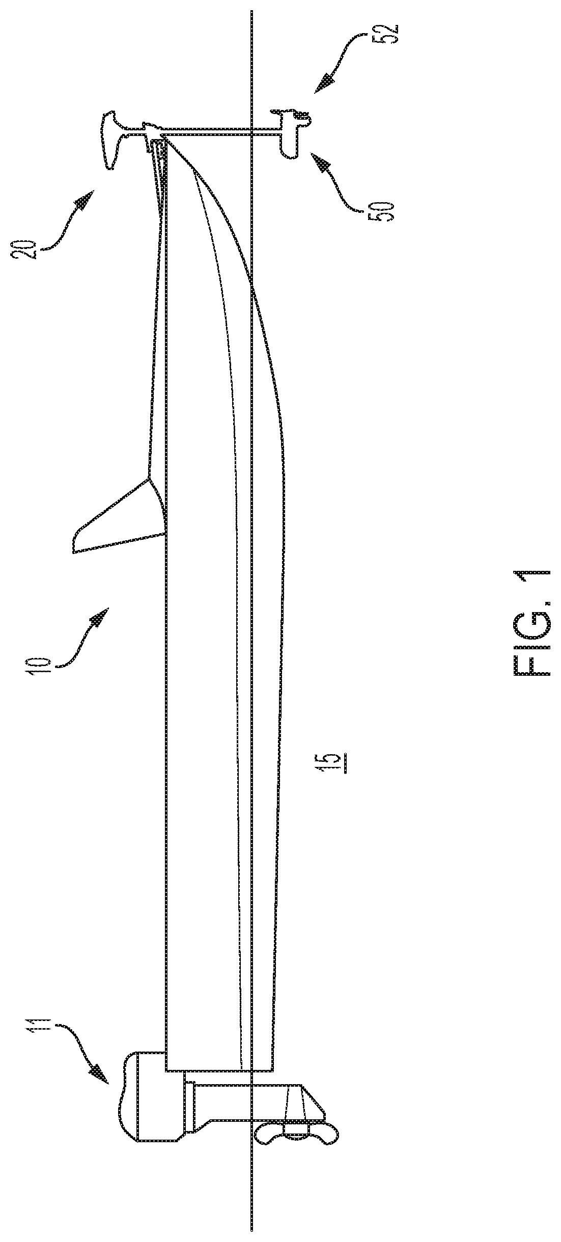
[0063]FIG. 1 illustrates an example watercraft 10 on a body of water 15. The watercraft 10 has a trolling motor assembly 20 attached to its front, with a propulsion motor 50 submerged in the body of water. According to some example embodiments, the trolling motor assembly 20 may include the propulsion motor 50, a propeller 52, and a navigation control device used to control the speed and the course or direction of propulsion. The trolling motor assembly 20 may be attac...


PUM


Abstract

A user input assembly for controlling operation of a trolling motor assembly including a propulsion motor is provided herein. The user input assembly includes a support plate and a foot pedal defining a top surface that is configured to receive a user's foot thereon. The foot pedal is pivotably mounted to the support plate. A deflection sensor is in communication with the foot pedal and is configured to detect an angle of orientation of the foot pedal and output a signal corresponding with the angle of orientation of the foot pedal. The signal is receivable by a controller that is configured to control a direction of the propulsion motor of the trolling motor assembly. A feedback device is coupled with the foot pedal and configured to, in response to pivotal movement of the foot pedal about the first axis, provide a resistance force to the pivotal movement.

Description

FIELD OF THE INVENTION[0001]Embodiments of the present invention relate generally to trolling motor assemblies and, more particularly, to systems, assemblies, and associated methods for controlling a trolling motor assembly.BACKGROUND OF THE INVENTION[0002]Trolling motors are often used during fishing or other marine activities. The trolling motors attach to the watercraft and propel the watercraft along a body of water. For example, trolling motors may provide secondary propulsion or precision maneuvering that can be ideal for fishing activities. The trolling motors, however, may also be utilized for the main propulsion system of watercraft. Accordingly, trolling motors offer benefits in the areas of ease of use and watercraft maneuverability, among other things. That said, further innovation with respect to the operation / control of trolling motors is desirable. Applicant has developed systems, assemblies, and methods detailed herein to improve capabilities of trolling motors.BRIEF...

Claims


Application Information

Patent Timeline
Patent Type & Authority Patents(United States)
IPC IPC(8): B63H20/00B63H20/08B63H20/14B63H21/21B63H20/12
CPCB63H20/007B63H20/08B63H21/21B63H20/14B63H20/12G05G1/445G05G5/03
Inventor SALISBURY, ALEXSCHROEDER, JEREMY J.BAILEY, PAUL ROBERT
Owner NAVICO HLDG
Why Eureka
Try Eureka