
Housing assembly for an integrated display unit

a display unit and integrated technology, applied in the direction of display/control unit casings, electrical apparatus casings/cabinets/drawers, identification means, etc., can solve the problems of time-consuming and expensive process of making the display unit compatible with the outer shell, design changes and compromises, added manufacturing complexity, cost, etc., to reduce complexity, cost, weight, and simplify the effect of design

Active Publication Date: 2020-03-24
MFG RESOURCES INT INC
View PDF155 Cites 2 Cited by
  • Summary
  • Abstract
  • Description
  • Claims
  • Application Information

AI Technical Summary

Benefits of technology

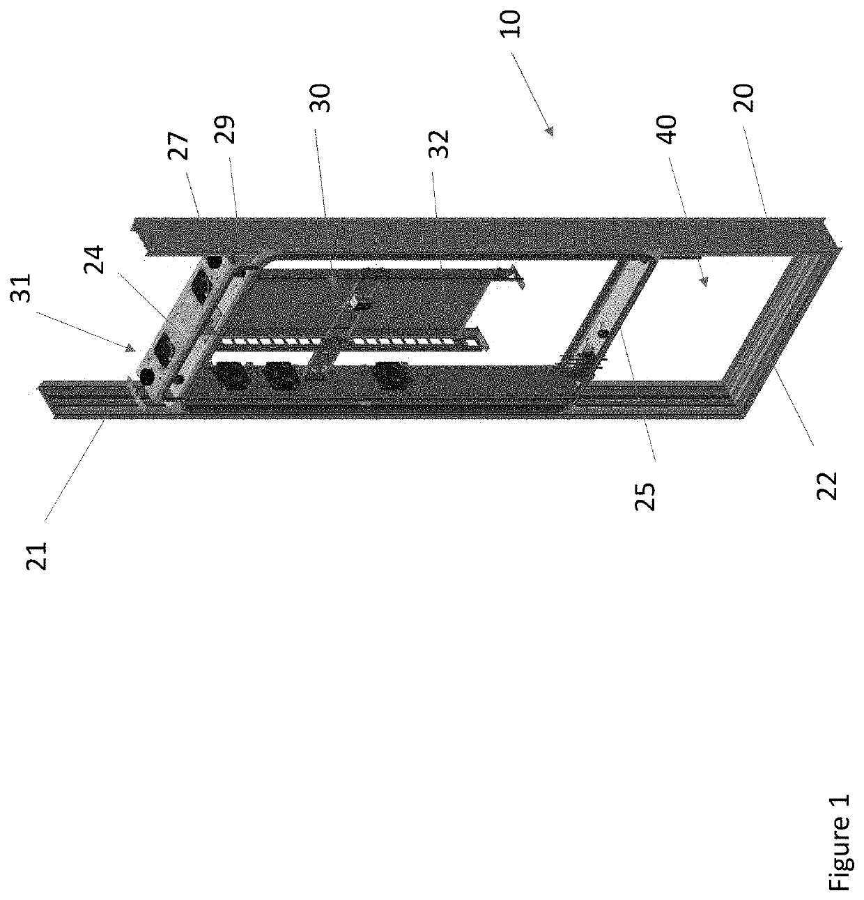
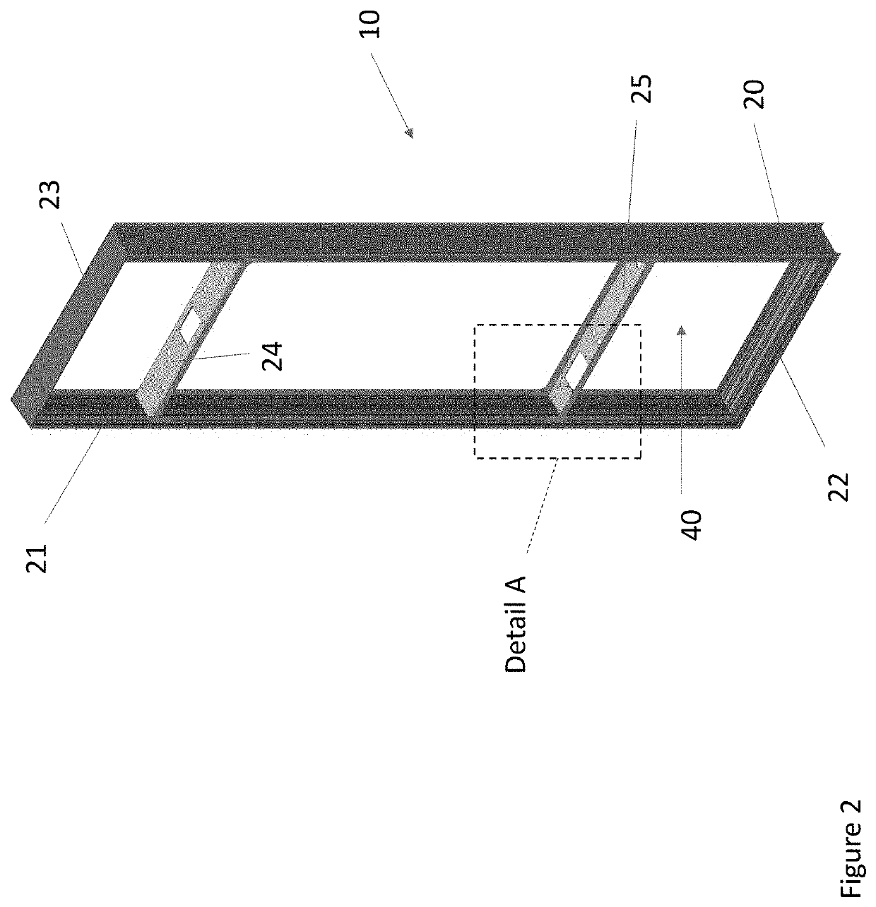
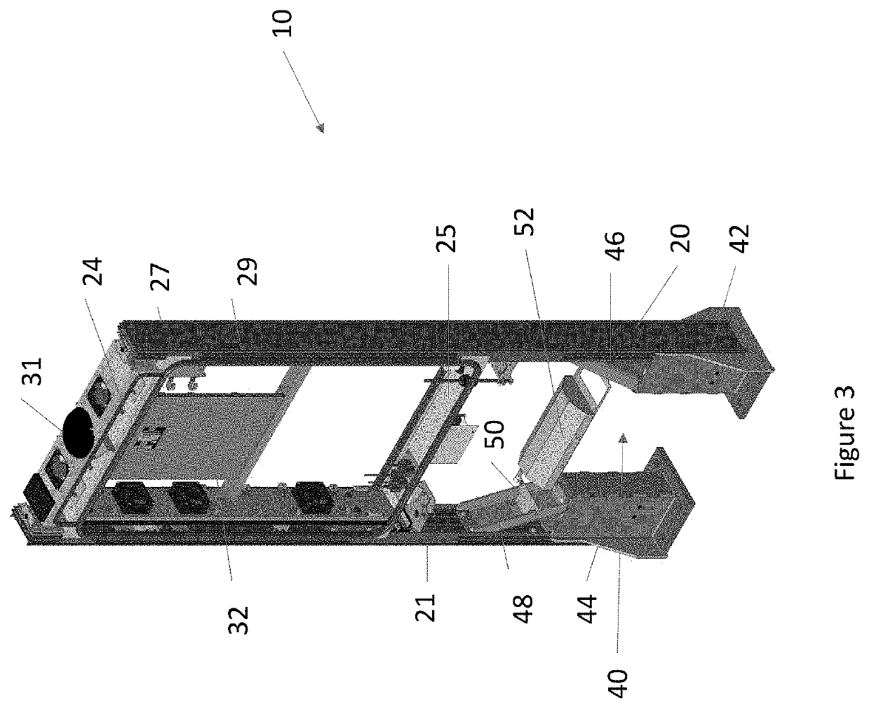
The patent text describes a need for a more efficient and cost-effective way to design and manufacture display units for use in outer shells. The text proposes a solution using a housing assembly for an integrated display unit that reduces complexity and weight. The assembly includes first and second side housing members that form the side walls of the display unit and extend vertically from a bottom horizontal member. This seals the display unit and simplifies the design process.

Problems solved by technology

Alternatively, or in addition, as space is often limited in such public locations, the outer shell may be provided in the form of street furniture such as, but not limited to, benches, bus shelters, kiosks, wayfinding units, telephone booths, or the like.
The processing of making the display unit compatible with the outer shell is time consuming and expensive and often requires design changes and compromises by both parties.
Such an arrangement results in added manufacturing complexity, weight, cost, and the like.

Method used


Image

  • Housing assembly for an integrated display unit
  • Housing assembly for an integrated display unit
  • Housing assembly for an integrated display unit

Examples


Embodiment Construction

)

[0026]Various embodiments of the present invention will now be described in detail with reference to the accompanying drawings. In the following description, specific details such as detailed configuration and components are merely provided to assist the overall understanding of these embodiments of the present invention. Therefore, it should be apparent to those skilled in the art that various changes and modifications of the embodiments described herein can be made without departing from the scope and spirit of the present invention. In addition, descriptions of well-known functions and constructions are omitted for clarity and conciseness.

[0027]Embodiments of the invention are described herein with reference to illustrations of idealized embodiments (and intermediate structures) of the invention. As such, variations from the shapes of the illustrations as a result, for example, of manufacturing techniques and / or tolerances, are to be expected. Thus, embodiments of the invention ...


PUM

PropertyMeasurementUnit
transition areaaaaaaaaaaa
vertical heightaaaaaaaaaa
compatibilityaaaaaaaaaa

Abstract

A housing assembly for an integrated display unit is provided. The display unit display unit comprises an open loop pathway for ambient air, a closed loop pathway for circulating gas, and at least one electronic display. A first and second horizontal member extend between a vertically extending first and second side member and are secured within a first channel and a second channel. The first and second side members form exterior side surfaces of the display unit to define, in part, the closed loop pathway. The first horizontal member forms an upper surface of the display unit and the second horizontal member forms a lower surface of the display unit to further define, in part, the closed loop pathway.

Description

CROSS-REFERENCE TO RELATED APPLICATION[0001]This application claims the benefit of U.S. Provisional Patent Application Ser. No. 62 / 711,908 filed Jul. 30, 2018, which is hereby incorporated by reference in its entirety.TECHNICAL FIELD[0002]Exemplary embodiments relate generally to a system and method for providing a housing assembly for an integrated display unit.BACKGROUND AND SUMMARY OF THE INVENTION[0003]Electronic displays and associated equipment are increasingly being used in cities and other urban environments, shopping malls, retail outlets, restaurants, sporting venues, universities, educational centers, medical facilities, and other business and public locations for advertising, messaging, wayfinding, public emergency notifications, and the like. Such electronic displays are often placed in partially or completely ruggedized units, to protect the various components of the electronic displays and associated equipment from the environmental elements, vandalism, and the like. ...

Claims


Application Information

Patent Timeline
Patent Type & Authority Patents(United States)
IPC IPC(8): H05K7/00H05K7/20H05K5/00H05K5/02B29C48/12B29L31/00
CPCH05K5/0017H05K7/20972H05K5/0213B29C48/12B29L2031/003G09F9/30G09F27/005H05K5/0018
Inventor DUNN, WILLIAM
Owner MFG RESOURCES INT INC
Learn More