
Variable venturi device with adjustable valve stem

a venturi device and valve stem technology, which is applied in the direction of valve operating means/releasing devices, mechanical equipment, transportation and packaging, etc., can solve the problems of inability to accurately inject product at inability to inject small, continuous quantities of product into the feeder fluid, and inability to accurately inject product. the desired rate and concentration,

Active Publication Date: 2020-03-24
CHAPIN MFG INC
View PDF45 Cites 1 Cited by
  • Summary
  • Abstract
  • Description
  • Claims
  • Application Information

AI Technical Summary

Benefits of technology

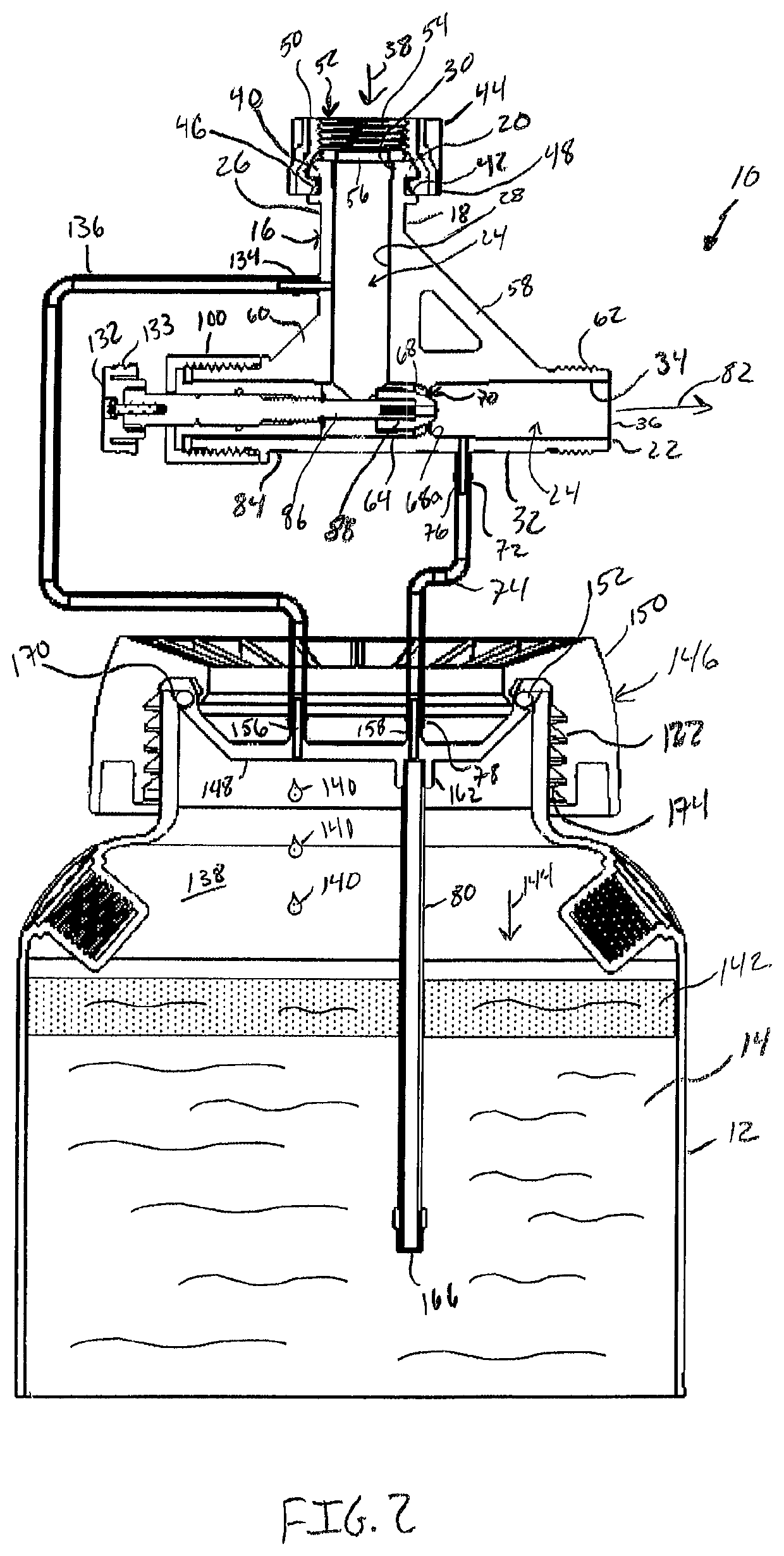
[0009]In accordance with a further aspect of the present invention, the container may include a closure. The closure may comprise a lid, a seal and a collar. The lid may have a top face and an opposing bottom face. First and second nibs may extend outwardly from the top face and a ring may extend inwardly from the bottom face. The ring is in fluid communication with the second nib. The lid may further include a circumferential groove. The seal is configured to be received within the groove where the seal is proportioned to seat against a mouth opening of the container to form an airtight seal therebetween. The collar is configured to overlap at least a portion of the lid and is mountable to the container to removably secure the lid to the container and facilitate the airtight seal.
[0010]In a further aspect of the present invention, the diverter tube is coupled to the first nib and the injection tube is coupled to the second nib. The lid may further include a product injection tube coupled to the ring at a first end, wherein the first end is fluidly connected to the injection tube, and configured to reside within the product at a second end. The collar may also include a set of collar threads, with the container including a corresponding set of container threads. The collar may threadably engage the container to secure the lid. The collar may freely wind and unwind upon the container threads without causing the lid to rotate.

Problems solved by technology

Fluid injection systems, such as sprayers, suffer from a number of drawbacks.
First, current systems fail to accurately inject product at the desired rate and concentration.
These and other systems are also unable to inject small, continuous quantities of product into the feeder fluid so as to produce a diluted product at low concentration.
However, such systems require multiple components making adjusting the feed rate and resultant dilution difficult and time consuming.

Method used


Image

  • Variable venturi device with adjustable valve stem
  • Variable venturi device with adjustable valve stem
  • Variable venturi device with adjustable valve stem

Examples


Embodiment Construction

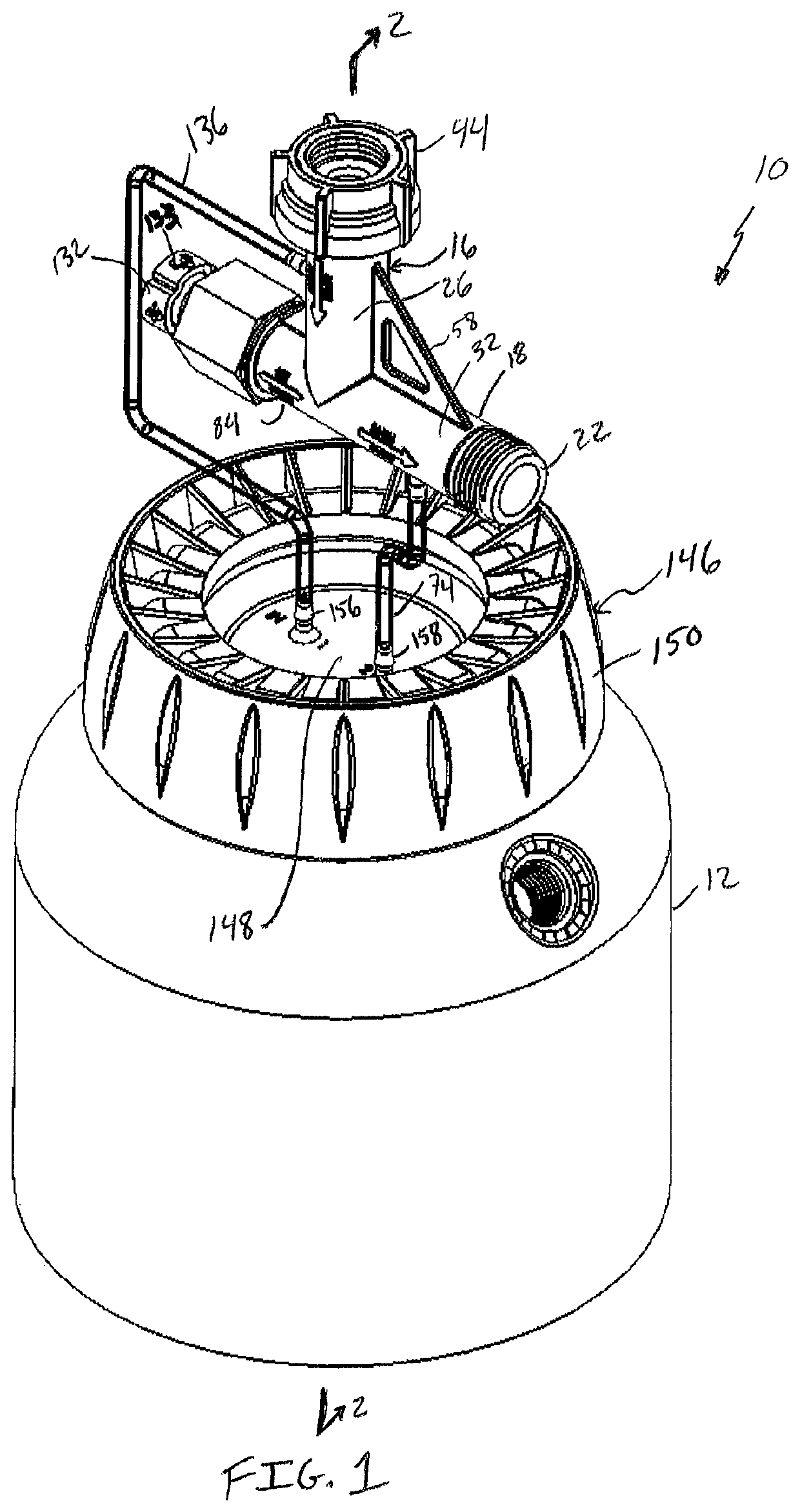
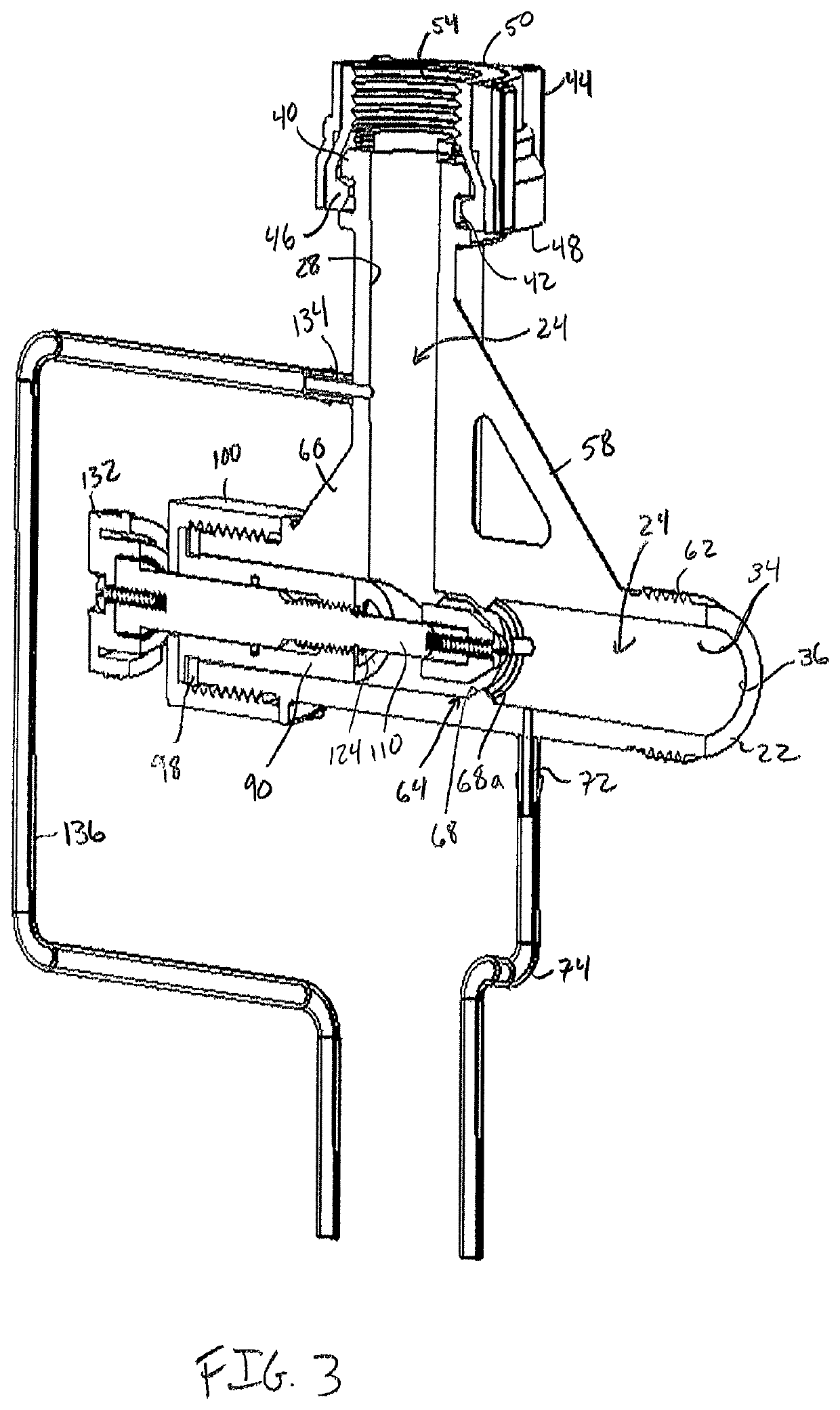
[0021]Referring now to FIGS. 1 and 2 there is shown a fluid injection system 10 in accordance with an aspect the present invention. Fluid injection system 10 may generally include a container 12 configured to hold a product 14 therein. Product 14 may be a dry soluble product or may be a product solution. Non-limiting examples of suitable products may include pesticides, herbicides or fertilizers. Coupled to container 12 is a fluid injection device 16. Fluid injection device 16 generally includes a housing 18 having opposing first and second ends 20, 22 defining a fluid pathway 24 therebetween. In accordance with an aspect of the present invention, housing 18 comprises an inlet arm 26 defining an inlet tube 28 having an inlet orifice 30 at first end 20 and an outlet arm 32 defining an outlet tube 34 having an outlet orifice 36 at second end 22 (see also FIGS. 3-5). Inlet tube 28 and outlet tube 34 may be oriented at an angle with respect to one another such that fluid pathway 24 is n...


PUM


Abstract

A fluid injection device includes a housing and a valve stem. The housing includes an inlet arm having an inlet orifice for receiving a feeder fluid. An outlet arm has an outlet orifice to discharge a mixed fluid. A venturi tube is between the inlet and outlet arms. The inlet arm, veturi tube and outlet arm define a nonlinear fluid pathway where the venturi tube redefines a portion of the nonlinear fluid pathway as a constricted fluid pathway. A diverter port is used to divert a portion of the feeder fluid from the inlet arm into the container and an injection port is used to receive product from the container. A valve arm is collinearly aligned with the venturi tube and the valve stem is positioned within the valve arm and adjusts the volume of the constricted fluid pathway.

Description

CROSS REFERENCE TO RELATED APPLICATIONS[0001]This application claims the benefit of U.S. Provisional Patent Application No. 62 / 534,383, filed Jul. 19, 2017, which is hereby incorporated by reference in its entirety.FIELD OF THE INVENTION[0002]The present invention generally relates to fluid injection systems and devices for dispensing a diluted product from a container, and more particularly to a fluid injection system and device comprising a venturi tube for drawing product from the container to dilute and dispense the diluted product, and still more particularly to a fluid injection system and device comprising an adjustable variable venturi tube for selectively controlling the spray application of the diluted product.BACKGROUND OF THE INVENTION[0003]Fluid injection systems, such as sprayers, suffer from a number of drawbacks. First, current systems fail to accurately inject product at the desired rate and concentration. For instance, some systems require continuous dilution of th...

Claims


Application Information

Patent Timeline
Patent Type & Authority Patents(United States)
IPC IPC(8): B01F5/04F16K1/04F16K1/06F16K31/50F16K1/38B05B12/14F16K1/48B05B7/24F16K11/00B01F5/00B05B15/30B05B7/04
CPCB01F5/0413B01F5/0496F16K1/385F16K1/487F16K1/06B05B12/1418F16K1/04B05B7/2443F16K31/50B01F5/043F16K19/00B05B7/0408B01F2215/0009B05B15/30B01F2005/0435B01F2005/0436B01F2005/004B01F25/312511B01F25/312512B01F25/31243B01F25/316B01F2101/04B01F25/312B01F2025/9191
Inventor DUBIEL, DAVID
Owner CHAPIN MFG INC
Learn More