Systems and methods for automation of low-flow groundwater sampling
a low-flow groundwater and system technology, applied in the direction of testing water, instruments, borehole/well accessories, etc., can solve the problems of enormous effort and time savings, achieve time-, labor- and cost-saving, save effort and time, and monitor groundwater contamination efficiently
- Summary
- Abstract
- Description
- Claims
- Application Information
AI Technical Summary
Benefits of technology
Problems solved by technology
Method used
Image
Examples
example 1
w Groundwater Sampling System
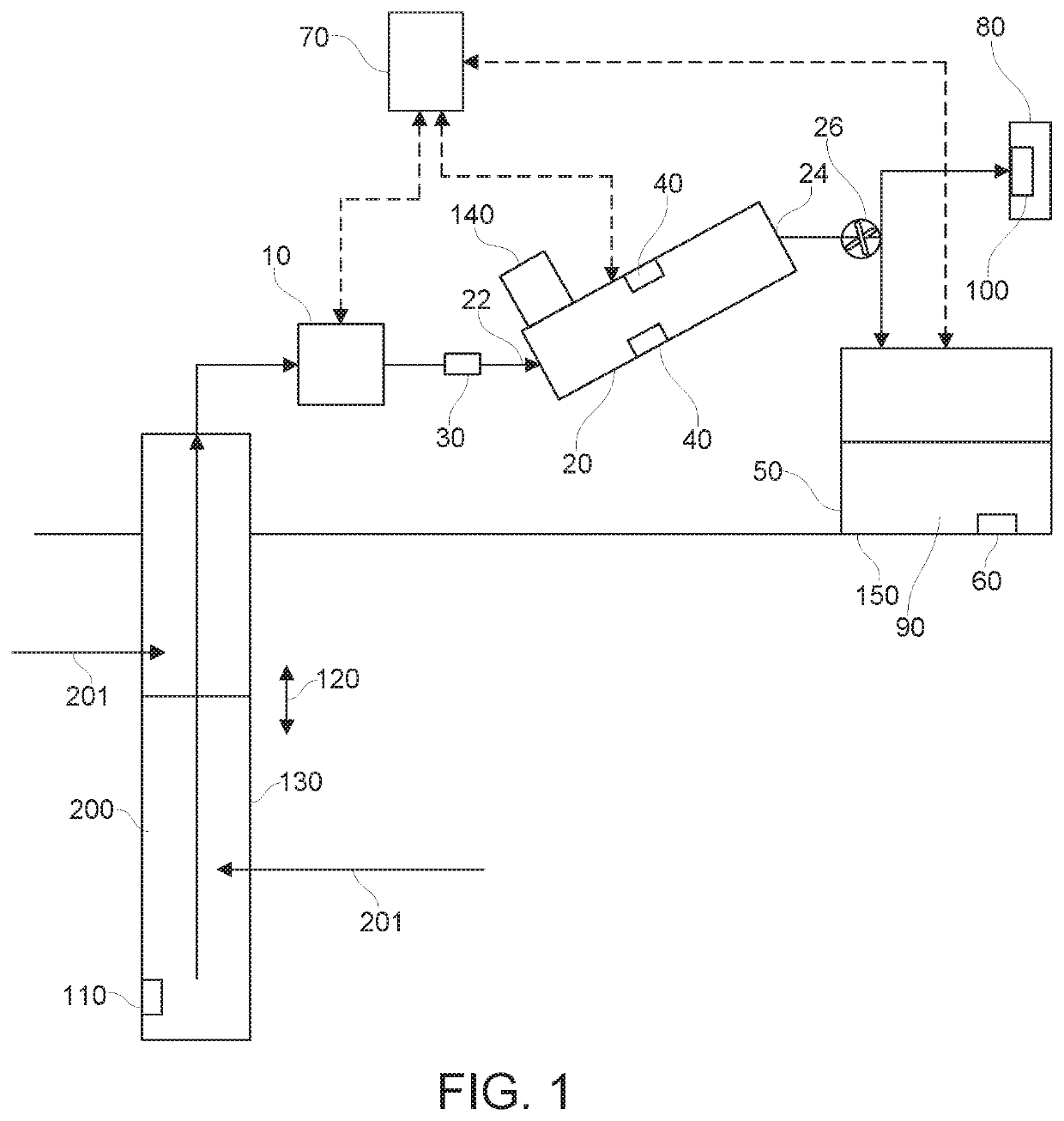
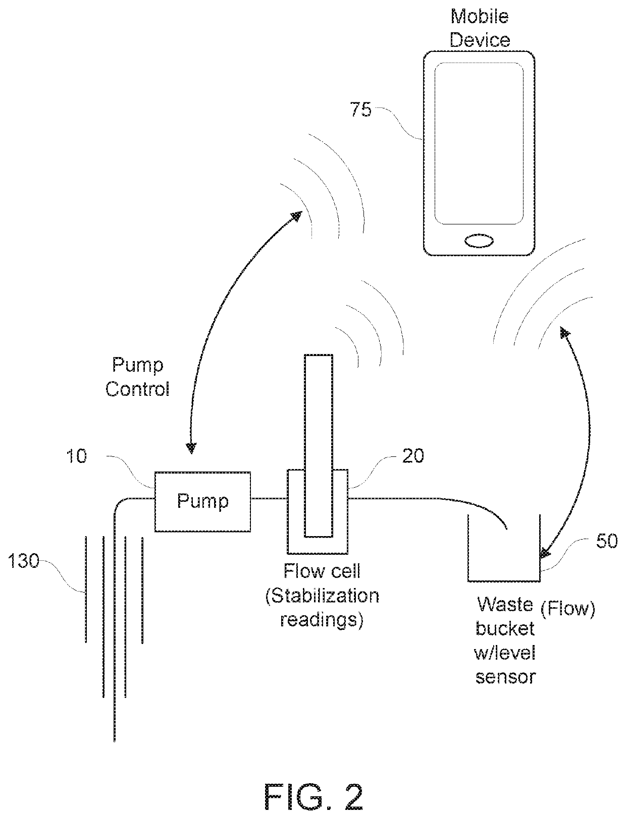
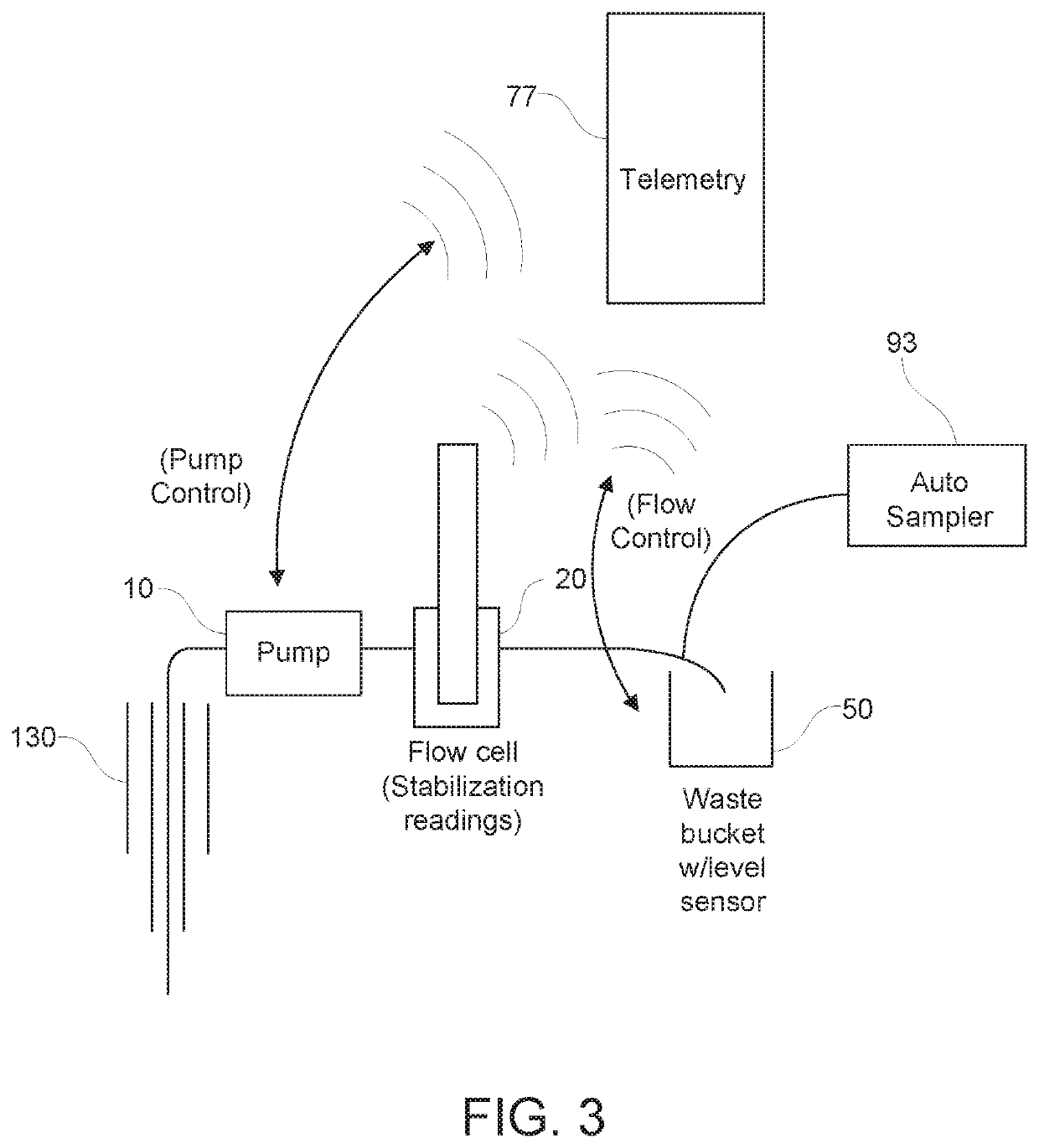
[0081]FIGS. 1-3 are schematic overviews of a system for automation of low-flow groundwater fluid sampling. Low flow pump 10 pumps fluid 200, such as groundwater that has entered and been collected in a well 130 as indicated by arrows 201, to a flow cell 20. The system optionally includes a separate flow sensor 30. Well 130 may be a monitoring well for monitoring possible contamination of groundwater. The flow cell 20 is in fluid and electronic communication with the low flow pump 10. In this manner, the measured parameters by the flow cell may be used to, in turn, control pump, thereby establishing a feedback control. The flow cell 20 may have one or more fluid quality sensors 40 for measuring one or more fluid parameters. The flow cell may have an inlet port 22 for delivering fluid to the flow cell and outlet port 24 for removal of fluid from the flow cell. Valves 26 may be used to control flow of fluid to either waste container 50 or to fluid sample co...
example 2
er Sampling System
[0093]FIG. 5 is a method 402 for monitoring groundwater according to an embodiment of the disclosure. FIG. 6 is a schematic illustration of a groundwater sampling system 400 according to another embodiment of the disclosure. In an example, method 402 is implemented and / or performed, at least in part, using the system 400 shown in FIG. 6. FIG. 7 is state diagram of a control scheme 510 for groundwater sampling. FIG. 8 is a prophetic example of a fluid stabilization condition, as determined by a turbidity sensor. Initially, as the pump is engaged and liquid is pumped to the flow cell, there may be initially high turbidity, due to long-term build-up prior to testing. The sensor(s) can be used to evaluate when a type of steady-state is achieved, indicating the fluid sample is “clean”, as determined by magnitude of deviation 930, such as a standard deviation or maximum deviation from an average over a certain number of fluid sample measurements or time period 932.
[0094]...
PUM
| Property | Measurement | Unit |
|---|---|---|
| Oxidation/Reduction Potential | aaaaa | aaaaa |
| volumes | aaaaa | aaaaa |
| volumes | aaaaa | aaaaa |
Abstract
Description
Claims
Application Information
 - R&D
- Intellectual Property
- Life Sciences
- Materials
- Tech Scout
- Unparalleled Data Quality
- Higher Quality Content
- 60% Fewer Hallucinations
Browse by: Latest US Patents, China's latest patents, Technical Efficacy Thesaurus, Application Domain, Technology Topic, Popular Technical Reports.
© 2025 PatSnap. All rights reserved.Legal|Privacy policy|Modern Slavery Act Transparency Statement|Sitemap|About US| Contact US: help@patsnap.com


