


Quick Research
Generate reliable direction feasibility study reports for your R&D in just a few steps.

Technical Q&A
Discover and master advanced knowledge NOW. Basics, ideas, possibilities, all at once.

Find Solutions
As an expert in R&D theories, this can generate solutions to your technical problems instantly.

Evaluate Feasibility
Analyze your overall solution with one click, know your potential R&D risks in advance.

Monitor Landscape
Get weekly tech updates, stay abreast of the latest tech innovations and key insights.
Liquid ejection head and liquid ejection apparatus
a liquid ejection and liquid ejection technology, which is applied in the direction of power drive mechanisms, printing, inking apparatus, etc., can solve the problems of increasing the size of the ejection head, changing or deteriorating in an electrically connected state, and accumulating static electricity in the user, so as to reduce the influence of static electricity and increase the mounting force, the effect of saving spa
- Summary
- Abstract
- Description
- Claims
- Application Information
AI Technical Summary
Benefits of technology
Problems solved by technology
Method used
Image


Examples
first embodiment
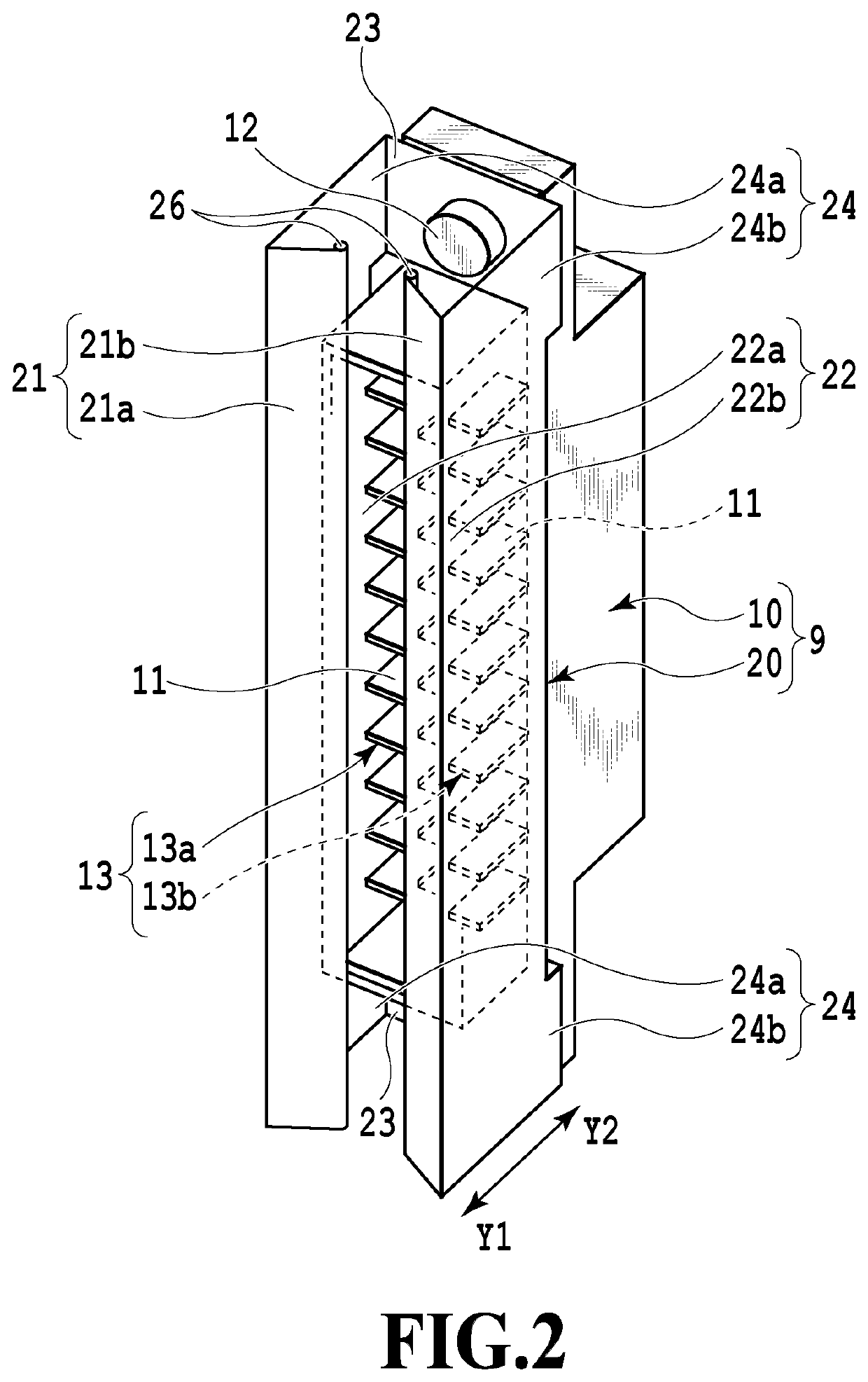
[0027]FIG. 1 is an appearance perspective view showing the entire configuration of a liquid ejection head according to the first embodiment of the present invention. FIG. 2 is a perspective view showing a configuration of a connector unit provided in the liquid ejection head shown in FIG. 1. FIG. 3A is a side view of the liquid ejection head shown in FIG. 1, and FIG. 3B is a partially enlarged view of a cross section taken along a line IIIB-IIIB of FIG. 3A.
[0028]A liquid ejection head 1 in the present embodiment shown in FIG. 1 is an inkjet print head of a line type (hereinafter simply referred to as a print head). At the bottom of the liquid ejection head 1, a print element board 2 is arranged throughout the liquid ejection head in a width direction. At least one print element board 2 may be provided, and in a case of providing a plurality of print element boards 2, they may be arranged in a staggered manner along the longitudinal direction of the print head. In the present embodim...
second embodiment
[0045]Next, the second embodiment of the present invention will be described. FIG. 6 is a perspective view of a grounding member 20A used for a liquid ejection head (print head) 1A according to the second embodiment. Further, FIGS. 7A and 7B are views showing the print head 1A according to the second embodiment. Specifically, FIG. 7A is a front view and FIG. 7B is a cross-sectional enlarged view taken along a line VIIB-VIIB of FIG. 7A. FIG. 8 is a cross-sectional enlarged view showing the state in which a connector unit 9 of the second embodiment is connected to the body connector 32.
[0046]The print head (liquid ejection head) 1A of the second embodiment includes the grounding member 20A as shown in FIG. 6. As for the grounding member 20A, a length Le of a web 22a is formed to be longer than a length Ld of the inclined face of a flange 21a, and an arm 24a is formed to be short. Meanwhile, a length Lf of a web 22b is equal to or less than a length Ld of the inclined face of a flange ...
third embodiment
[0051]Next, the third embodiment of the present invention will be described. FIG. 9 is a perspective view of a grounding member 20B used for a liquid ejection head (print head) 1B in the third embodiment. FIGS. 10A and 10B are views showing the print head 1B of the third embodiment. Specifically, FIG. 10A is a front view and FIG. 10B is a cross-sectional enlarged view taken along a line XB-XB of FIG. 10A. FIG. 11 is a cross-sectional enlarged view showing the state in which a connector unit 9B is connected to the body connector 32 in the third embodiment.
[0052]The print head (liquid ejection head) 1B of the third embodiment has the grounding member 20B as shown in FIG. 9. As for the grounding member 20B, as in the second embodiment, a length Lf of the web 22b is formed to be equal to or less than a length Ld of the flange 21b. However, in the present embodiment, a length Le of the web 22a is also formed to be equal to or less than a length Ld of the flange 21a. This aspect differs f...
PUM
 Abstract
Description
Claims
Application Information
 - R&D Engineer
- R&D Manager
- IP Professional
- Industry Leading Data Capabilities
- Powerful AI technology
- Patent DNA Extraction
Browse by: Latest US Patents, China's latest patents, Technical Efficacy Thesaurus, Application Domain, Technology Topic, Popular Technical Reports.
© 2024 PatSnap. All rights reserved.Legal|Privacy policy|Modern Slavery Act Transparency Statement|Sitemap|About US| Contact US: help@patsnap.com