
System and method for detecting damaged tool of multi-axis head machining equipment

a multi-axis head and machining equipment technology, applied in the direction of process and machine control, process control, instruments, etc., can solve the problems that equipment or machining defects cannot be fundamentally prevented during machining, equipment itself may be damaged, and machining defects may be caused, so as to prevent the damage to equipment caused by damaged tools, the operation rate and productivity of machining equipment can be enhanced.

Active Publication Date: 2020-03-17
HYUNDAI MOTOR CO LTD +1
View PDF10 Cites 1 Cited by
  • Summary
  • Abstract
  • Description
  • Claims
  • Application Information

AI Technical Summary

Benefits of technology

Enables accurate detection of damaged tools during machining, preventing equipment damage and enhancing operational efficiency and productivity by ensuring timely tool replacement.

Problems solved by technology

In the multi-axis head machining equipment, some of the tools may be damaged during a machining operation, and in this case, due to the damaged tool, the equipment itself may be damaged or machining defects may be caused.
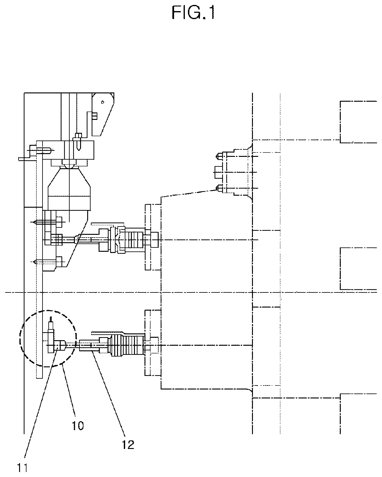
The above contact-type device 10 for detecting the damaged tool has a problem that since it is impossible to detect the damaged tool during machining, damage to equipment or machining defects cannot be fundamentally prevented during machining.
However, it is difficult for such a non-contact type device for detecting the damaged tool to be applied to a multi-axis head machining equipment composed of multi spindles and a single spindle motor, and this device has a problem that since it is difficult to detect a load applied to the spindle shaft during a machining operation in which a machining load is small, it is impossible to detect the damaged tool.
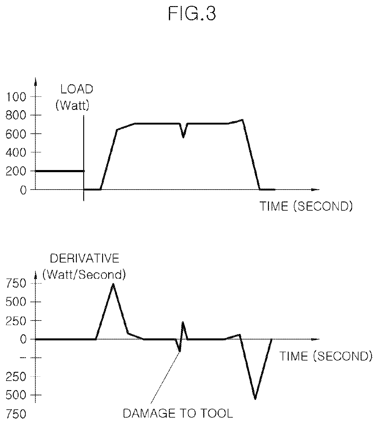
In addition, the multi-axis head machining equipment may generate a tool replacement alarm at the time of terminating machining when the abnormality of the tool is detected by energy monitoring in the damaged tool detecting device.
In addition, when the abnormality is detected in monitoring the energy, the multi-axis head machining equipment may generate a tool replacement alarm at the time of terminating machining.

Method used


Image

  • System and method for detecting damaged tool of multi-axis head machining equipment
  • System and method for detecting damaged tool of multi-axis head machining equipment
  • System and method for detecting damaged tool of multi-axis head machining equipment

Examples


Embodiment Construction

[0030]It is understood that the term “vehicle” or “vehicular” or other similar term as used herein is inclusive of motor vehicles in general such as passenger automobiles including sports utility vehicles (SUV), buses, trucks, various commercial vehicles, watercraft including a variety of boats and ships, aircraft, and the like, and includes hybrid vehicles, electric vehicles, plug-in hybrid electric vehicles, hydrogen-powered vehicles and other alternative fuel vehicles (e.g. fuels derived from resources other than petroleum). As referred to herein, a hybrid vehicle is a vehicle that has two or more sources of power, for example both gasoline-powered and electric-powered vehicles.

[0031]The terminology used herein is for the purpose of describing particular embodiments only and is not intended to be limiting of the disclosure. As used herein, the singular forms “a,”“an” and “the” are intended to include the plural forms as well, unless the context clearly indicates otherwise. It wil...


PUM


Abstract

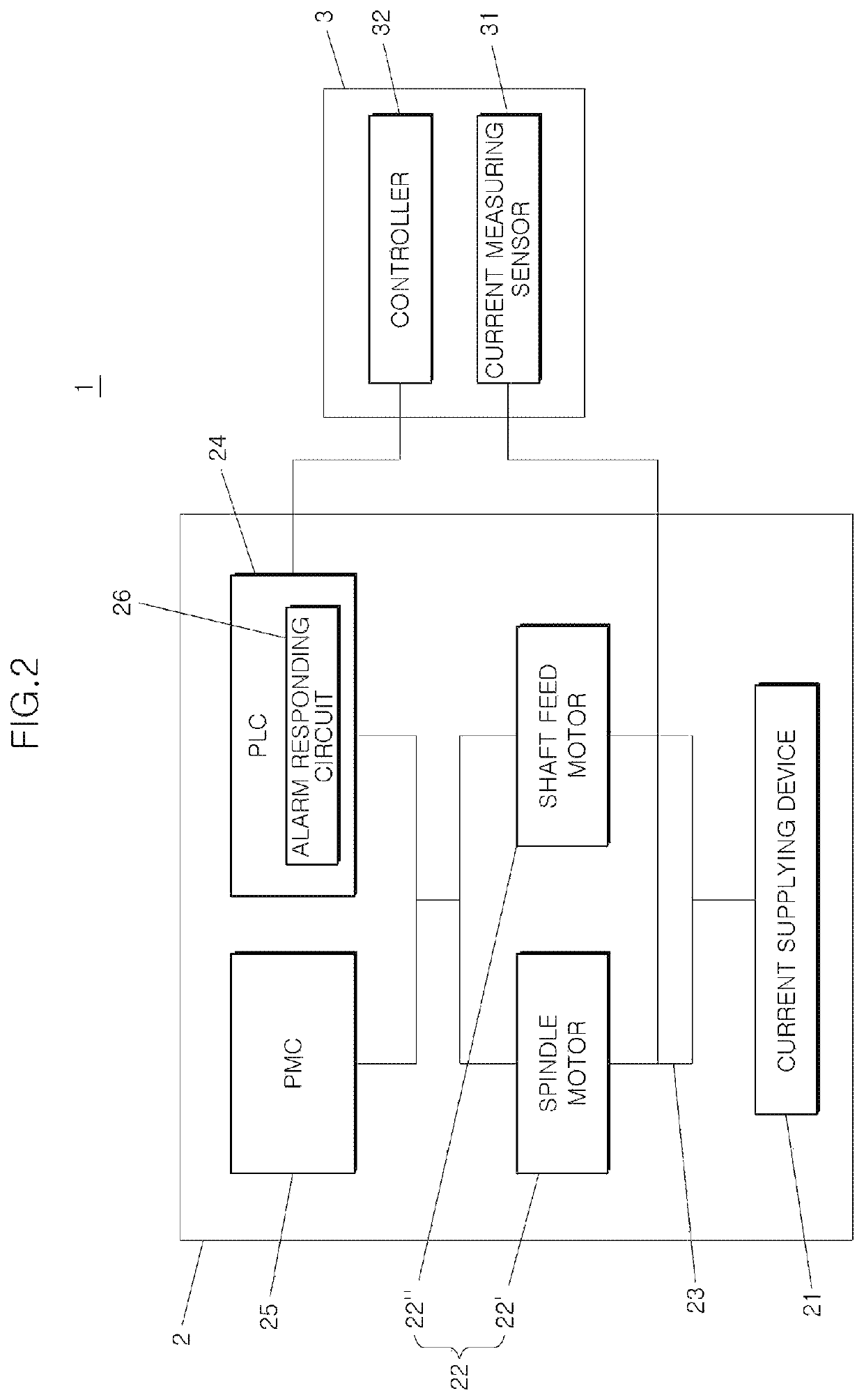
A system for detecting a damaged tool of multi-axis head machining equipment includes multi-axis head machining equipment, and a damaged tool detecting device connected to the multi-axis head machining equipment to detect a damaged tool, the damaged tool detecting device being configured to measure a current and a current change amount of the multi-axis head machining equipment to monitor a machining load, and a derivative and machining energy of the machining load, so as to detect whether there is an abnormality in a plurality of tools mounted on a multi-axis head during machining.

Description

CROSS-REFERENCE TO RELATED APPLICATION(S)[0001]This application claims under 35 U.S.C. § 119(a) the benefit of Korean Patent Application No. 10-2017-0147789, filed on Nov. 8, 2017, the entire contents of which are incorporated herein by reference.BACKGROUND(a) Technical Field[0002]The present disclosure relates to a system and method for detecting a damaged tool of multi-axis head machining equipment, and more particularly, to the system and method for detecting the damaged tool capable of correctly detecting whether there is an abnormality in a plurality of tools mounted on a multi-axis head, using machining load monitoring, derivative monitoring, and energy monitoring.(b) Description of Related Art[0003]Multi-axis head machining equipment refers to equipment for machining a metallic workpiece and the like using a plurality of tools mounted on multi spindles thereof, and may include a spindle motor for rotating the multi spindles and a shaft feed motor for linearly moving the multi...

Claims


Application Information

Patent Timeline
Patent Type & Authority Patents(United States)
IPC IPC(8): B23Q17/09G08B21/18B23Q39/00
CPCB23Q17/0957G08B21/187B23Q17/0961B23Q2039/006G05B19/4065
Inventor KIM, HO-HWANPARK, YOONG-JECHOI, DAE-HAN
Owner HYUNDAI MOTOR CO LTD
Learn More