Method for operating an inductive conductivity meter and respective conductivity meter

a conductivity meter and inductive technology, applied in the direction of material analysis, material testing goods, instruments, etc., can solve problems such as errors in the determination of the electrical and achieve the effect of improving the accuracy of the determination of the conductivity of the medium

Active Publication Date: 2020-03-10
KROHNE MESSTECHNICK GMBH & CO KG
View PDF13 Cites 0 Cited by
  • Summary
  • Abstract
  • Description
  • Claims
  • Application Information

AI Technical Summary

Benefits of technology

[0008]Thus, the object of the invention is to provide a method for operating an inductive conductivity meter and an inductive conductivity meter, in which the accuracy of a determination of a conductivity of a medium is improved compared to the prior art.
[0015]The invention is based on the finding that the electrical conductivity of the medium, which inductively couples the transmitting coil and the receiving coil with one another, is a parameter both in the input impedance and in a transfer function which describes the transmission of electrical alternating signals between the transmitting coil terminal and the receiving coil terminal. If, for example, a given transmitting alternating signal is fed into the transmitting coil terminal of the transmitting coil and if the conductivity of the medium changes, the input impedance changes, on the one hand, and, on the other hand, the receiving alternating signal at the receiving coil terminal correspondingly changes. By adjusting the terminating impedance, which, like the conductivity, is also a parameter in both the input impedance and the transfer function, such that the input impedance is again matched to the setpoint input impedance, as before the change in conductivity, the effect on the input impedance due to the change in the electrical conductivity of the medium is compensated. Thus, information about the change in the conductivity of the medium is contained in the change in the terminating impedance. This makes it possible to determine the conductivity of the medium using the adjusted input impedance and the set terminating impedance.
[0019]The method according to the invention has the advantage over methods known from the prior art that the determination of the conductivity of the medium is more accurate. The higher accuracy results, in particular, in that a change in the input impedance is compensated for and not measured, as is known from the prior art. As a result, the range of values of the amplitudes to be measured is less than the range of values that the amplitudes to be measured known from the prior art assume, so that inaccuracies in the measurement of amplitudes are smaller. The technical effort to implement the method is comparable to the technical effort for implementing the method known from the prior art.
[0021]In a further implementation of the method, it is provided that the input impedance is adjusted to the setpoint input impedance such that the input impedance corresponds to the setpoint input impedance. Thus, not only does the real part of the input impedance correspond to the real part of the setpoint input impedance, but also the imaginary part of the input impedance corresponds to the imaginary part of the setpoint input impedance. On the one hand, if the real parts and, on the other hand, the imaginary parts correspond to one another, the accuracy of determining the conductivity of the medium is increased as compared with a method in which only the real parts correspond to one another. Two real parts or two imaginary parts correspond, in particular, to one another when they have the same value.

Problems solved by technology

However, a problem in determining an amplitude such as the amplitude of the receiving alternating signal is that the accuracy of the determination is not constant over the entire range of values that the amplitude can assume, which can lead to errors in the determination of the electrical conductivity of the medium.

Method used


Image

  • Method for operating an inductive conductivity meter and respective conductivity meter
  • Method for operating an inductive conductivity meter and respective conductivity meter
  • Method for operating an inductive conductivity meter and respective conductivity meter

Examples


Embodiment Construction

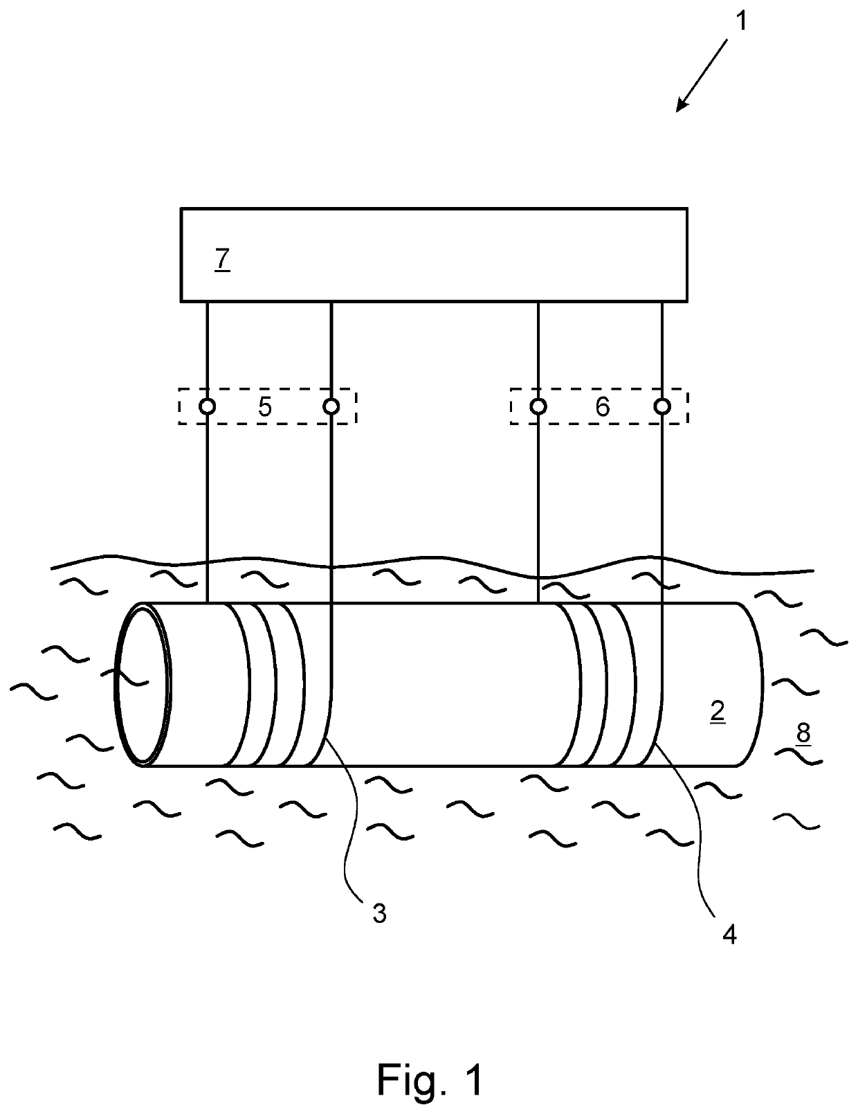
[0036]FIG. 1 shows the inductive conductivity meter 1. The inductive conductivity meter 1 has the hollow-cylindrical carrier 2, on which the transmitting coil 3 and the receiving coil 4 are arranged. The transmitting coil 3 and the receiving coil 4 are arranged on the hollow cylindrical carrier 2 by being wound around the hollow cylindrical carrier 2, wherein the transmitting coil 3 has the number N1 turns and the receiving coil 4 has the number N4 turns. Furthermore, the transmitting coil 3 has the electrical transmitting coil terminal 5 and the receiving coil 4 has the electrical receiving coil terminal 6. The inductive conductivity meter 1 also has the control device 7, which is designed to control the transmitting coil 3 and the receiving coil 4, which is why the control device 7 is also electrically connected to the transmitting coil terminal 5 of the transmitting coil 3 and to the receiving coil terminal 6 of the receiving coil. In addition, a setpoint input impedance is store...


PUM

PropertyMeasurementUnit
input impedanceaaaaaaaaaa
impedanceaaaaaaaaaa
conductivityaaaaaaaaaa

Abstract

A method for operating an inductive conductivity meter having a transmitting coil, a receiving coil and a terminating impedance device, the transmitting coil having a transmitting coil terminal, the receiving coil having a receiving coil terminal and the terminating impedance device having a terminating impedance, wherein the receiving coil is terminated with the terminating impedance device and wherein the transmitting coil and the receiving coil are inductively coupled with one another by an electrically conductive medium. To provide an improved accuracy of a determination of a conductivity of a medium a setpoint input impedance is specified, an input impedance is determined at the transmitting coil terminal, the terminating impedance is set such that the input impedance is matched to the setpoint input impedance, and a conductivity of the medium is determined using the adjusted input impedance and the set termination impedance.

Description

BACKGROUND OF THE INVENTIONField of the Invention[0001]The invention relates to a method for operating an inductive conductivity meter. The inductive conductivity meter comprises a transmitting coil, a receiving coil and a terminating impedance device. Thereby, the transmitting coil has a transmitting coil terminal, the receiving coil has a receiving coil terminal, and the terminating impedance device has a terminating impedance. The receiving coil is terminated with the terminating impedance device and the transmitting coil and the receiving coil are inductively coupled with one another by an electrically conductive medium.[0002]In addition, the invention relates to an inductive conductivity meter. The inductive conductivity meter also has a transmitting coil, a receiving coil, a terminating impedance device and, additionally, a control device. Thereby, the transmitting coil has a transmitting coil terminal, the receiving coil has a receiving coil terminal, and the terminating impe...

Claims


Application Information

Patent Timeline
Patent Type & Authority Patents(United States)
IPC IPC(8): G01N27/02G01R27/22G01N27/08G01R27/26G01N33/18
CPCG01N27/023G01R27/2611G01R27/22G01N27/025G01N27/08G01N33/18G01N27/00
Inventor GLASMACHERS, HOLGER
Owner KROHNE MESSTECHNICK GMBH & CO KG
Why Eureka
Try Eureka