
Vision correction systems and methods for using an intraocular lens enclosed in an inner capsulated bag

a technology of intraocular lens and inner capsulation, which is applied in the field of ophthalmological surgery, can solve the problems of affecting the accuracy of vision correction, and affecting the accuracy of vision correction, and achieves good distance acuity and near visual acuity

Active Publication Date: 2020-03-03
INGRAM RONALD WILLIAM
View PDF2 Cites 2 Cited by
  • Summary
  • Abstract
  • Description
  • Claims
  • Application Information

AI Technical Summary

Benefits of technology

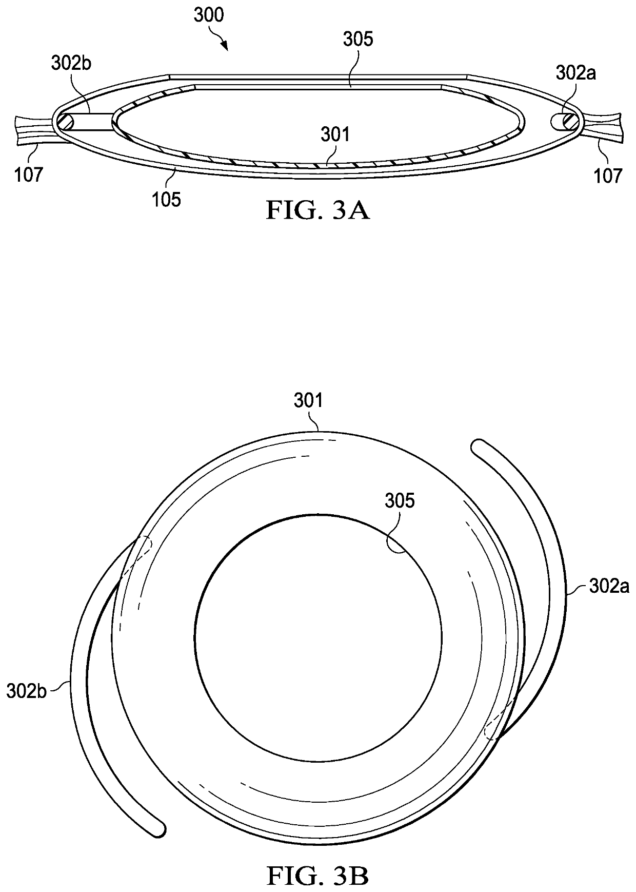
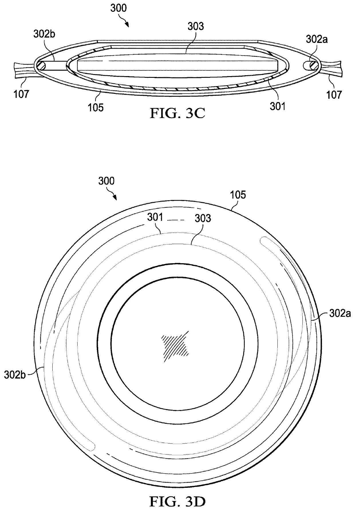
[0007]The principles of the present invention are embodied in vision correction systems and methods in which an inner (artificial) capsular bag and enclosed intraocular lens are inserted within the natural capsular bag of the eye. The inner capsular bag prevents the natural capsular bag from collapsing around the intraocular lens, which allows at least a part of the intraocular lens to move. Specifically, the intraocular lens is configured such that at least part of the intraocular lens can tilt and / or move forward, with respect to the cornea and retina, in response to gravitational force to create myopic astigmatism.
[0008]In other words, when the wearer is looking straight forward, the intraocular lens, which preferably includes a monofocal optic, remains substantially vertical within the eye to provide good distance acuity. When the wear looks downward, for example while reading, the resulting tilt of the optic of the intraocular lens creates myopic shift with or without astigmatism, which provides good near visual acuity.
[0009]Advantageously, because only a monofocal optic is required, the halos, glare, and / or compromised near visual acuity found with conventional multifocal lenses is substantially reduced or eliminated. The hinge system found with accommodating intraocular lenses is also eliminated.

Problems solved by technology

Among other things, since multifocal lenses typically have two focal points (i.e., near and distance), focus at intermediate points can be compromised.
Furthermore, the transitions between zones can result in halos and glare in high-contrast lighting situations, such as driving at night.
Finally, multifocal lenses are generally not suitable for persons working with fine details, such as reading small print or manipulating small objects.

Method used


Image

  • Vision correction systems and methods for using an intraocular lens enclosed in an inner capsulated bag
  • Vision correction systems and methods for using an intraocular lens enclosed in an inner capsulated bag
  • Vision correction systems and methods for using an intraocular lens enclosed in an inner capsulated bag

Examples


Embodiment Construction

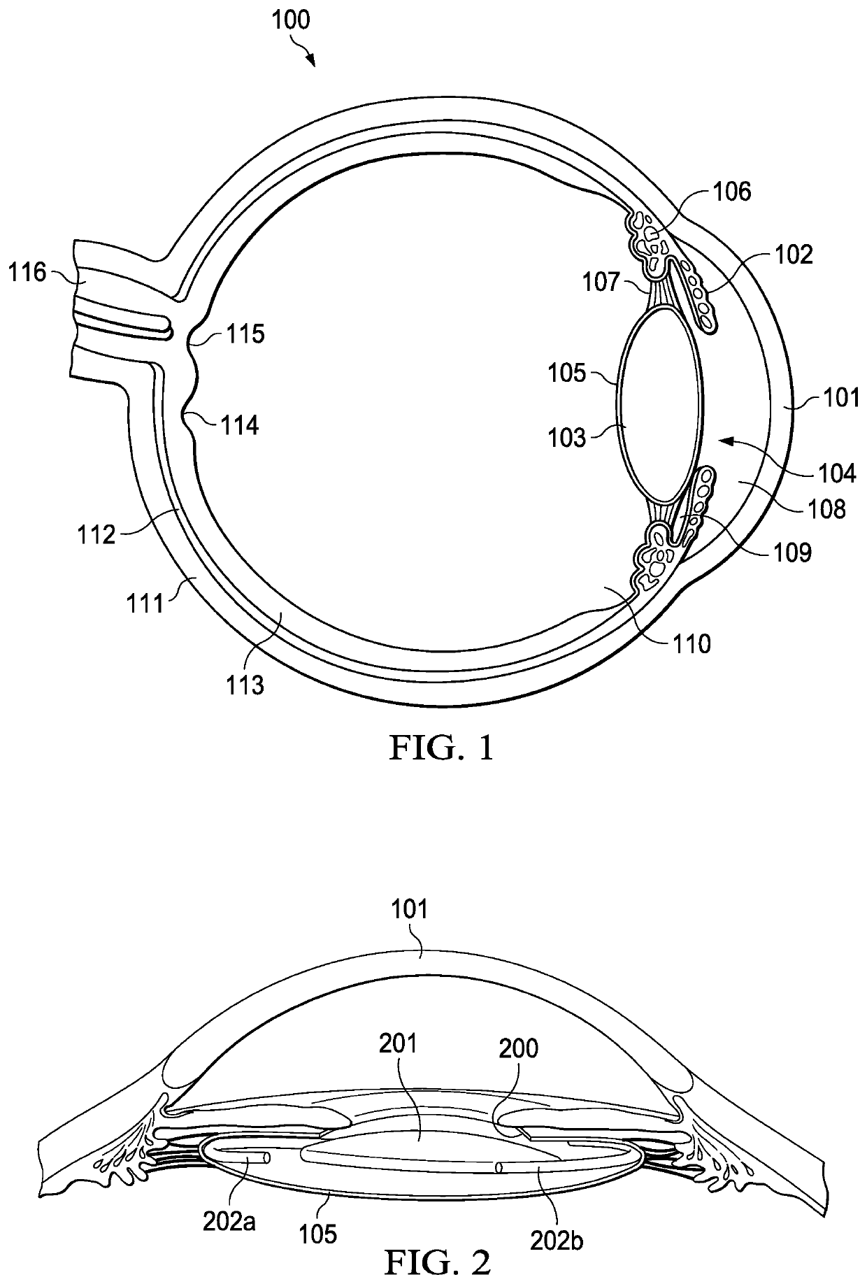
[0022]The principles of the present invention and their advantages are best understood by referring to the illustrated embodiment depicted in FIGS. 1-5 of the drawings, in which like numbers designate like parts.

[0023]FIG. 1 is a cross-sectional diagram illustrating the basic anatomy of a typical human eye 100. The primary structures include the cornea 101, iris 102, crystalline lens 103, and pupil 104. Lens 103 is enclosed by the capsular bag 105, which is supported by suspensory ligaments 107. The ciliary body 106 includes the ciliary muscle that controls focusing of capsular bag 105. The anterior chamber 108 spaces cornea 101 from the anterior portion of lens 103 and the anterior portion of iris 102. The posterior chamber 109 is disposed between the posterior portion of iris 102 and suspensory ligaments 107. The vitreous body 110 is disposed behind the posterior portion of capsular bag 105.

[0024]The sclera 111 or “white” of the eye provides the outer supporting wall of the eye an...


PUM


Abstract

A intraocular lens system includes an artificial capsular bag adapted for implantation within a natural capsular bag of an eye and an intraocular lens adapted to be received within the artificial capsular bag. At least a portion of the intraocular lens tilts and moves forwards within the artificial capsular bag under gravitational force with respect to a cornea and retina of the eye to create myopia.

Description

FIELD OF INVENTION[0001]The present invention relates in general to ophthalmological surgery, and in particular to vision correction systems and methods using an intraocular lens enclosed in an inner capsulated bag.BACKGROUND OF INVENTION[0002]Intraocular lenses are typically implanted into the human eye after cataract removal, as well as to correct large refractive errors, such as myopia (nearsightedness), hyperopia (farsightedness), and presbyopia (farsightedness due to the loss of crystalline lens elasticity with age). In aphakic implant surgery, which is commonly used during cataract removal, an opening is made through the anterior portion of the capsular bag surrounding the clouded crystalline lens, the lens is removed, and an intraocular lens is inserted into the remaining portion of the capsular bag. During phakic implantation, the intraocular lens is inserted without removal of the natural lens, typically to correct large refractive errors.[0003]Since the first introduction ...

Claims


Application Information

Patent Timeline
Patent Type & Authority Patents(United States)
IPC IPC(8): A61F2/16
CPCA61F2/1627A61F2002/16901
Inventor INGRAM, RONALD WILLIAM
Owner INGRAM RONALD WILLIAM
Learn More