
Suction roller, coating apparatus and apparatus for manufacturing membrane electrode assembly

a technology of coating apparatus and membrane electrode, which is applied in the direction of cell components, final product manufacturing, sustainable manufacturing/processing, etc., can solve the problems of gas sucking from an exterior space into the roller body, and achieve the effect of suppressing the deterioration of the members and suppressing the reduction of sucking for

Active Publication Date: 2020-02-25
DAINIPPON SCREEN MTG CO LTD
View PDF16 Cites 0 Cited by
  • Summary
  • Abstract
  • Description
  • Claims
  • Application Information

AI Technical Summary

Benefits of technology

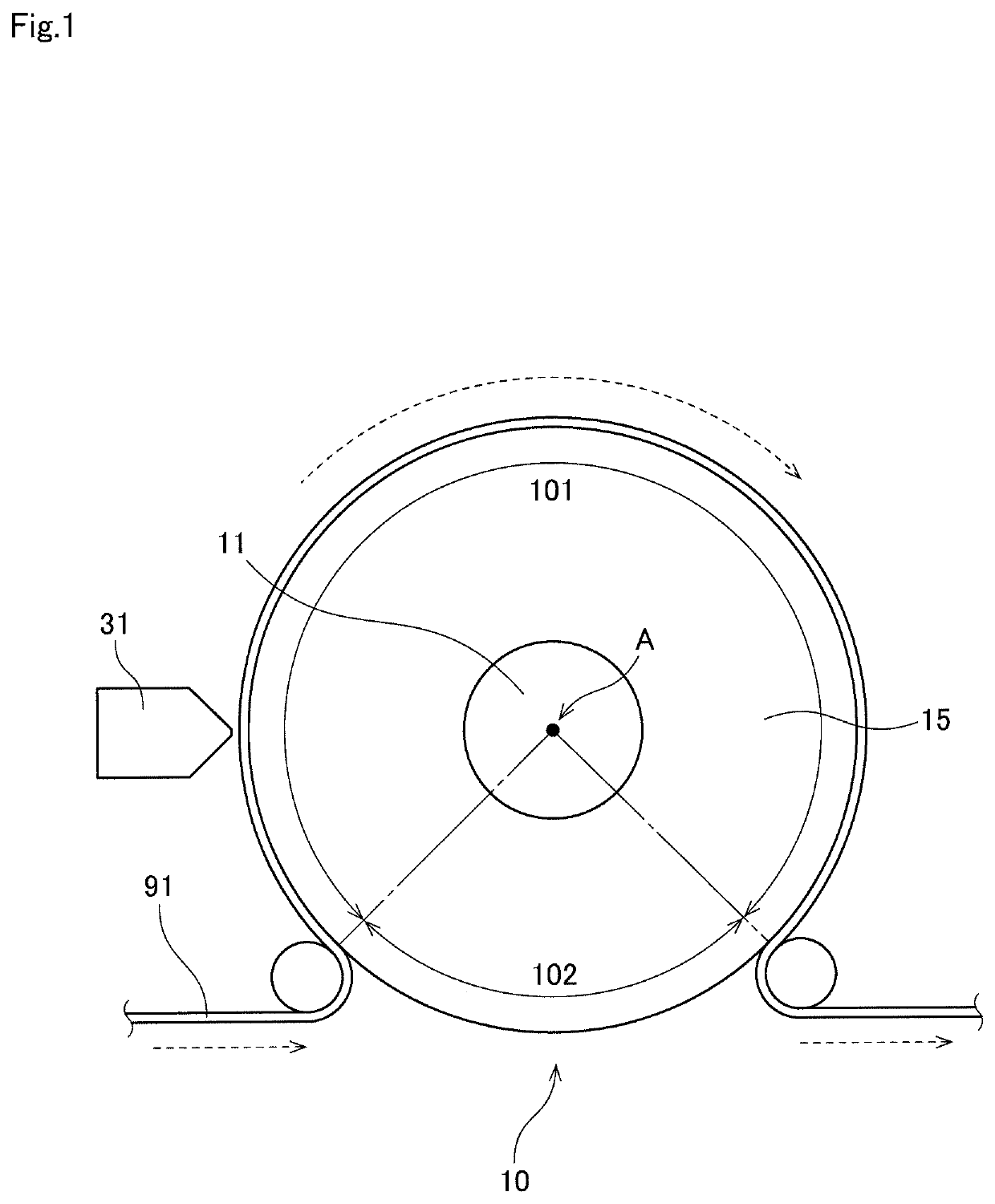
The present invention is aimed at providing a structure that prevents a reduction in suction force in a closed region of a suction roller due to gas entering from an open region of the roller surface. It also prevents deterioration of members due to slidable movement. The invention achieves this by using a base material that is held on the outer surface of the roller body using a negative pressure developed in suction holes. In the open region, gas cannot pass through the orifice opening, thus preventing a reduction in sucking force due to the entry of gas from the open region. The roller body, orifice plate, and side plate rotate as a unit, further preventing deterioration of members due to slidable movement.

Problems solved by technology

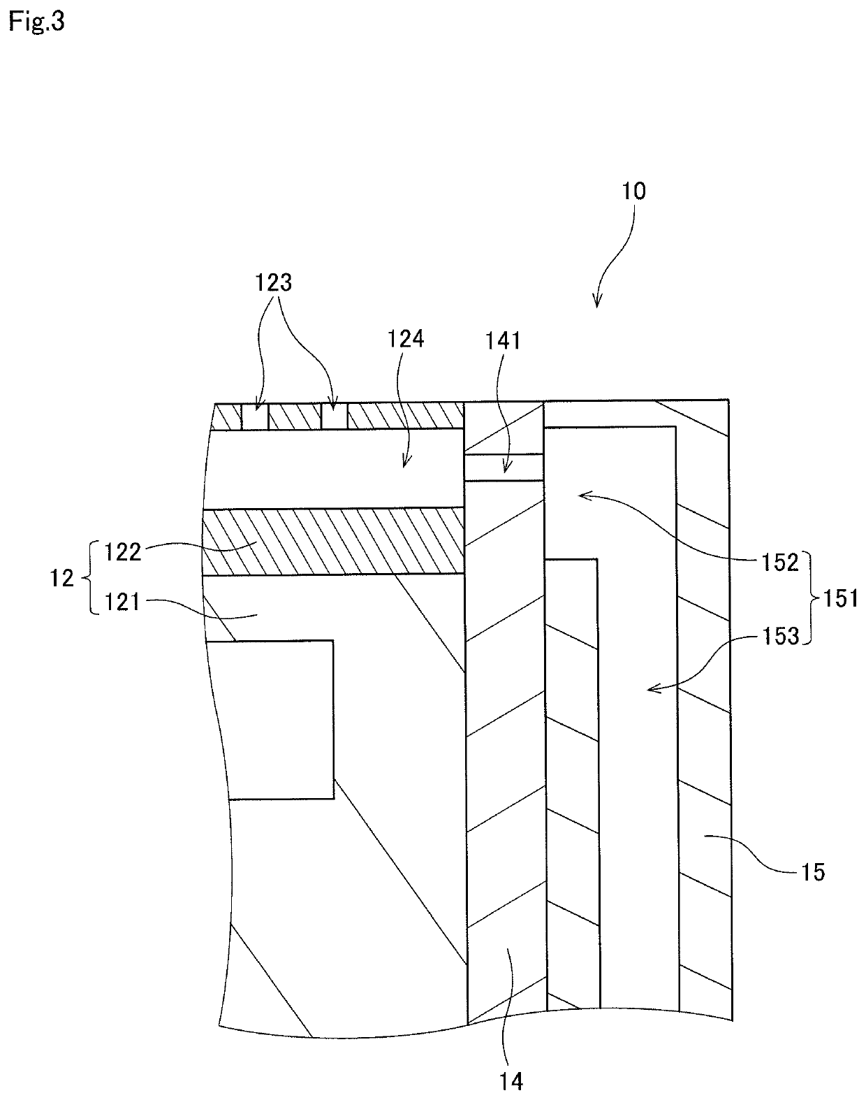
In the open region of the outer peripheral surface which is not covered with the base material, the sucking of a gas from an exterior space into the roller body is suppressed because it is difficult for the gas to pass through the orifice opening.

Method used


Image

  • Suction roller, coating apparatus and apparatus for manufacturing membrane electrode assembly
  • Suction roller, coating apparatus and apparatus for manufacturing membrane electrode assembly
  • Suction roller, coating apparatus and apparatus for manufacturing membrane electrode assembly

Examples


Embodiment Construction

A preferred embodiment according to the present invention will now be described with reference to the drawings.

<1. Configuration of Suction Roller>

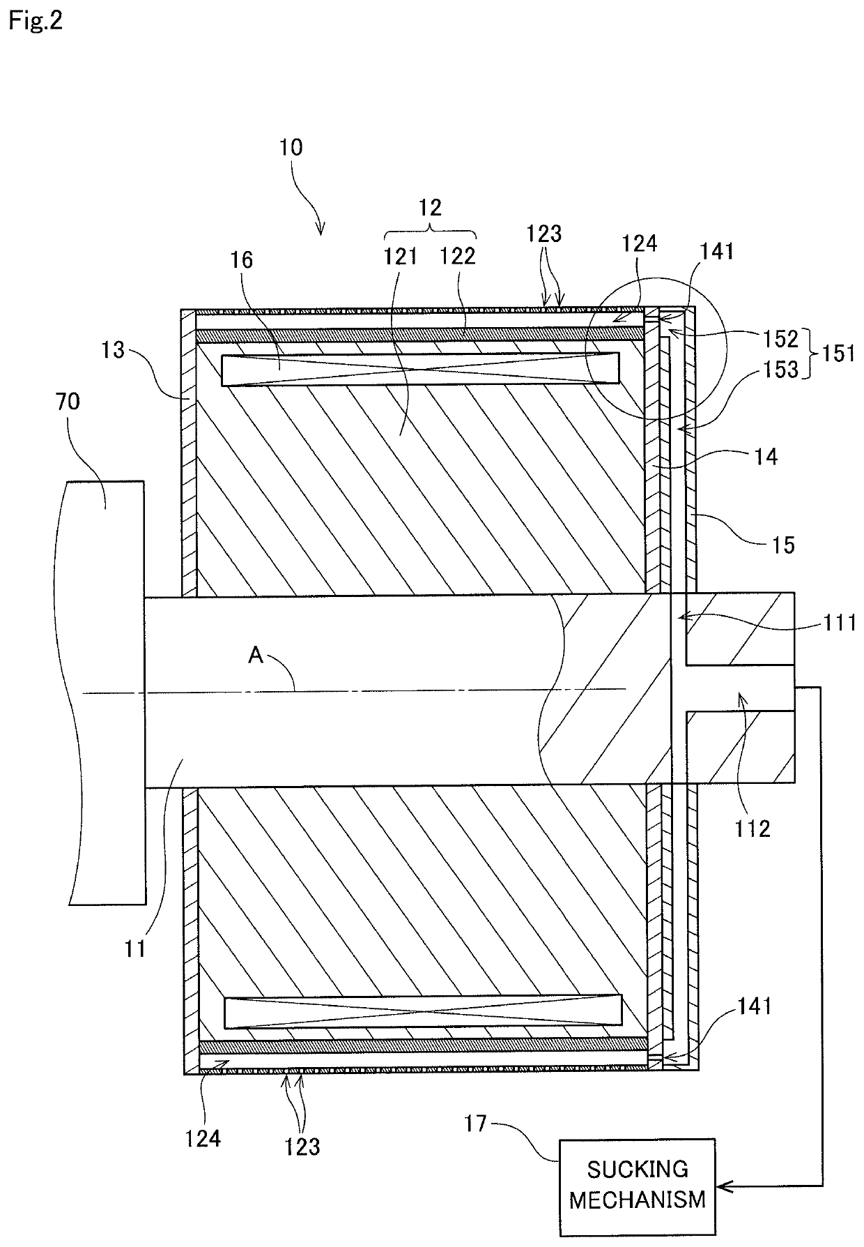
FIG. 1 is a side view of a suction roller 10 as seen in the direction of an axis A according to one preferred embodiment of the present invention. FIG. 2 is a sectional view of the suction roller 10 taken along a plane containing the axis A. This suction roller 10 is a roller that transports an elongated strip-shaped base material 91 by rotating about the axis A extending in a horizontal direction while holding the base material 91 thereon under suction. Specific examples of the base material 91 will be described later. The suction roller 10 has a cylindrical outer peripheral surface with a plurality of suction holes 123. When a manufacturing apparatus is in operation, a negative pressure (vacuum) is developed in the plurality of suction holes 123 by a sucking mechanism 17 conceptually shown in FIG. 2. The strip-shaped base material ...


PUM

PropertyMeasurementUnit
inner diameteraaaaaaaaaa
diameteraaaaaaaaaa
opening diameteraaaaaaaaaa

Abstract

An orifice plate having orifice openings is interposed between a roller body and a side plate. In a closed region of an outer peripheral surface of the roller body which is covered with a base material, the base material is held on the outer peripheral surface of the roller body under suction by a negative pressure developed in suction holes. In an open region of the outer peripheral surface which is not covered with the base material, the sucking of a gas from an exterior space into the roller body is suppressed because it is difficult for the gas to pass through the orifice openings. This suppresses a reduction in sucking force in the closed region due to the entry of the gas from the open region. The roller body, the orifice plate and the side plate rotate as a unit. This suppresses deterioration of the members due to the slidable movement thereof.

Description

BACKGROUND OF THE INVENTIONField of the InventionThe present invention relates to a suction roller rotating while holding a strip-shaped base material on part of an outer peripheral surface thereof under suction, and a coating apparatus and a membrane electrode assembly manufacturing apparatus both including the suction roller.Description of the Background ArtIn recent years, attention has been given to fuel cells as power sources for driving motor vehicles, mobile phones or the like. A fuel cell is a power generation system that generates electric power through an electrochemical reaction between hydrogen (H2) contained in a fuel and oxygen (O2) in the air. The fuel cell has advantages over other cells in its high power generation efficiency and low environmental load.There are several types of fuel cells that are different depending on electrolytes being used therein. One of these fuel cells is a polymer electrolyte fuel cell (PEFC) including an ion exchange membrane (electrolyte ...

Claims


Application Information

Patent Timeline
Patent Type & Authority Patents(United States)
IPC IPC(8): H01M4/88B65H27/00B29D99/00B32B37/00B32B38/00H01M8/1004H01M8/1018H01M4/04
CPCB29D99/005H01M4/881H01M4/8882B65H27/00H01M8/1004B32B38/00H01M4/8828B32B37/0053H01M4/8807H01M4/0404B65H2406/33H01M2008/1095B05C5/0245B05C9/14B05C13/02Y02E60/50Y02E60/10B05C5/02Y02P70/50
Inventor OGASAWARA, MITSUOTAKAGI, YOSHINORIOMORI, MASAFUMI
Owner DAINIPPON SCREEN MTG CO LTD
Learn More