Medical imaging apparatus with a housing

a medical imaging and housing technology, applied in the field of medical imaging apparatus, can solve the problems of troublesome high operating sound level and/or noise, and achieve the effect of advantageous noise suppression and protection from undesirable damage and/or deformation

Active Publication Date: 2020-02-25
SIEMENS HEALTHCARE GMBH
View PDF37 Cites 0 Cited by
  • Summary
  • Abstract
  • Description
  • Claims
  • Application Information

AI Technical Summary

Benefits of technology

An object of the present invention is to minimize sound transmission into the patient accommodation zone of a medical data detector during a medical imaging examination, in particular a magnetic resonance examination.
The at least one self-supporting cladding can be formed to be, or have, a cladding funnel. Such a cladding funnel is arranged on the front side or the rear side of the detector, around each or one end region of the patient accommodation zone (patient tunnel or bore). This has the advantage of making the cladding compact, particularly in noise-emitting and / or noise-transmitting zones of a medical imaging apparatus, such as a magnetic resonance apparatus. Such a cladding additionally permits advantageous noise suppression during operation of the medical imaging apparatus, such as a magnetic resonance apparatus. Using the least one self-supporting cladding as a cladding funnel on the front side or rear side of the detector additionally permits a visually smooth transition from the front side or rear side to the patient accommodation zone cladding of the housing.

Problems solved by technology

For example, in magnetic resonance examinations very high operating sound levels and / or noise may be caused by the interaction between gradient coils and the basic field magnet of a magnetic resonance scanner.
Patients find these high sound levels during the medical imaging examination troublesome.

Method used


Image

  • Medical imaging apparatus with a housing
  • Medical imaging apparatus with a housing
  • Medical imaging apparatus with a housing

Examples


Embodiment Construction

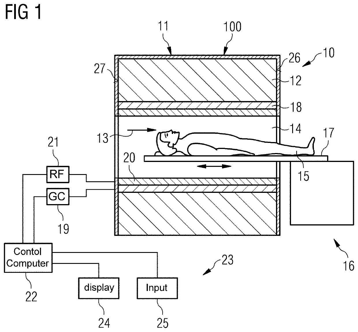
FIG. 1 schematically shows a medical imaging apparatus. In the present exemplary embodiment, the medical imaging apparatus is a magnetic resonance apparatus 10, so the present invention is explained using the example of the magnetic resonance apparatus 10. The present invention, however, is not limited to a configuration as a magnetic resonance apparatus 10, and further configurations of the medical imaging apparatus are possible.

The magnetic resonance apparatus 10 has a detector formed by a scanner 11. The scanner 11 has a superconducting basic field magnet 12 that generates a strong and constant basic magnetic field 13. The magnetic scanner 11 has a patient accommodation zone 14 for accommodating a patient 15. In the present exemplary embodiment, the patient accommodation zone 14 is of cylindrical shape and is circumferentially surrounded by the scanner 11. In principle, however, the patient accommodation zone 14 may formed in a manner that differs therefrom. The patient 15 can be...


PUM


Abstract

A medical imaging apparatus has medical image data detector, and a housing that at least partially surrounds the detector and has at least one cladding. The at least one cladding is a self-supporting cladding with a reinforcing grid and a resilient cladding layer.

Description

BACKGROUND OF THE INVENTIONField of the InventionThe present invention concerns a medical imaging apparatus with a medical image data detector and a housing that at least partially surrounds the detector, and that has a cladding.Description of the Prior ArtVery high operating sound levels may be generated during a medical imaging examination, in particular a magnetic resonance examination. For example, in magnetic resonance examinations very high operating sound levels and / or noise may be caused by the interaction between gradient coils and the basic field magnet of a magnetic resonance scanner. Patients find these high sound levels during the medical imaging examination troublesome.SUMMARY OF THE INVENTIONAn object of the present invention is to minimize sound transmission into the patient accommodation zone of a medical data detector during a medical imaging examination, in particular a magnetic resonance examination.The invention is based on a medical imaging apparatus, in partic...

Claims


Application Information

Patent Timeline
Patent Type & Authority Patents(United States)
IPC IPC(8): A61B5/055G01R33/34G01R33/38G01R33/385A61B5/00
CPCA61B5/704G01R33/3854A61B5/055G01R33/3802G01R33/34007G01R33/3403A61B2560/0406
Inventor MACIEJEWSKI, BERNDZINK, STEPHANMAMELI, MAURO
Owner SIEMENS HEALTHCARE GMBH
Why Eureka
Try Eureka