
Push-pull counter flow heat exchanger

a heat exchanger and push-pull technology, applied in the direction of heating types, stationary tubular conduit assemblies, stationary plate conduit assemblies, etc., can solve the problems of unthinkable benefits, and achieve the effect of reducing energy costs, improving the venting capacity of high moisture and contaminated areas

Active Publication Date: 2020-02-25
LES ENTREPRISES DE DEVEMENT DURABLE ENERGIE SOLUTIONS & ASSOCIES
View PDF20 Cites 0 Cited by
  • Summary
  • Abstract
  • Description
  • Claims
  • Application Information

AI Technical Summary

Benefits of technology

The solution enhances ventilation performance, reduces energy losses, minimizes moisture formation, and extends the heat exchanger's operational lifespan by improving heat recovery and reducing noise, while being cost-effective and adaptable for various installations.

Problems solved by technology

Such potential benefits are unthinkable in a standard heat exchanger venting apparatus.

Method used


Image

  • Push-pull counter flow heat exchanger
  • Push-pull counter flow heat exchanger
  • Push-pull counter flow heat exchanger

Examples


Embodiment Construction

A novel heat exchanger will be described hereinafter. Although the invention is described in terms of specific illustrative embodiments, it is to be understood that the embodiments described herein are by way of example only and that the scope of the invention is not intended to be limited thereby.

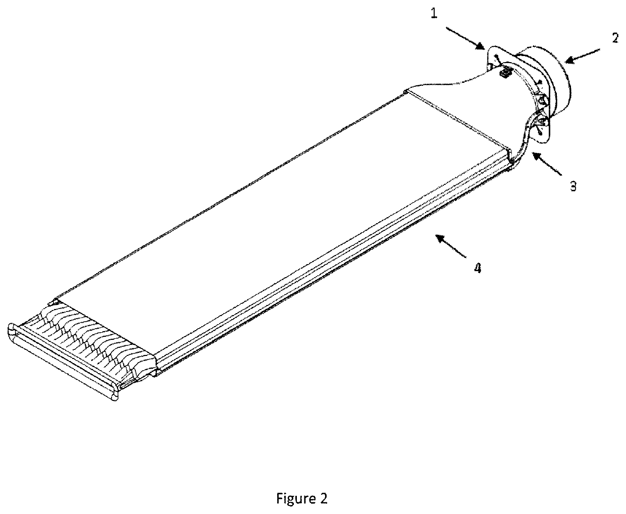
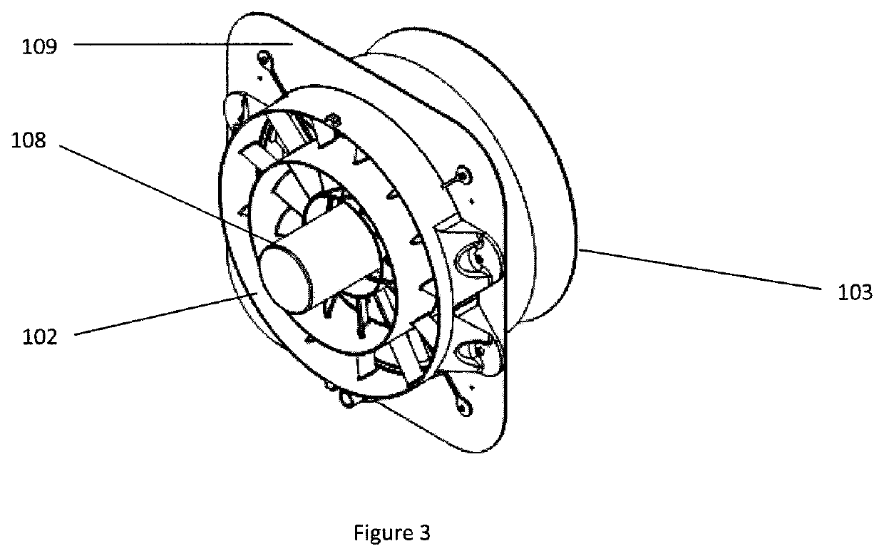
The heat exchanger assembly in accordance with the principle of the present invention aims at exchanging heat between exhausted or inside air, typically warm and / or contaminated air, and outside air, typically colder air or cleaner / fresher air. Now referring to FIG. 2, the Heat Exchanger Unit comprises a fan assembly (1), a shutter (2), a counter flow heat exchanger (4) and a plurality of plenums (3). The fan assembly (1) pulls air from outside through the shutter (2) and pushes the inside air through the counter flow heat exchanger (4) and the plurality of plenums (3) toward outside air. One of the functions of the shutter (2) is to stop the outside air from entering the unit while the fa...


PUM


Abstract

A Heat Exchanger Unit comprising a venting unit, a shutter, a counter flow heat exchanger and a plurality of plenums. The venting unit pulls the outside air, or fresh / purer air, from outdoor through the shutter while it pushes the exhausted inside air through the counter flow heat exchanger and the plurality of plenums toward outside air.

Description

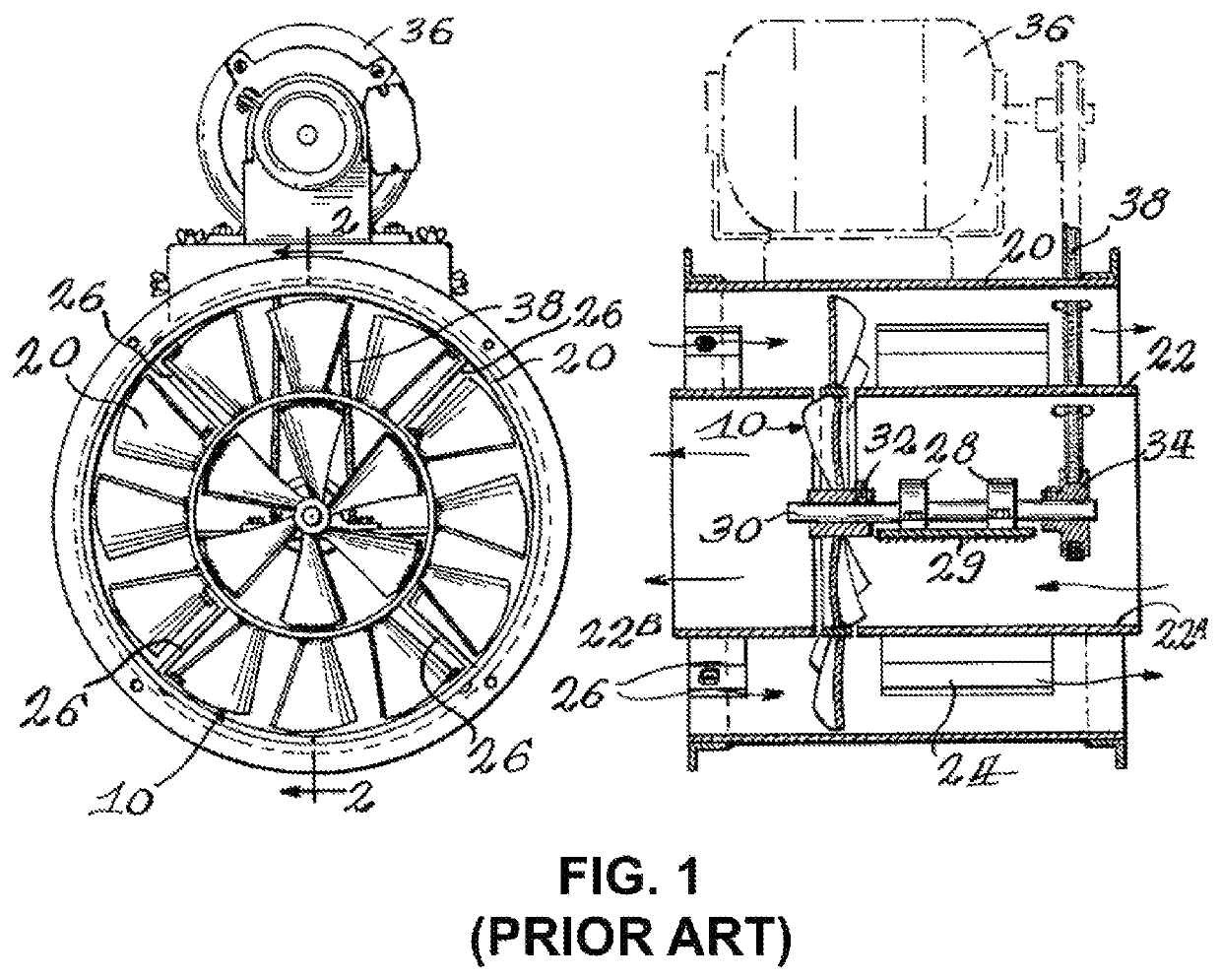
FIELD OF THE INVENTIONThe present invention relates in the general field of agrifood industry ventilation systems. In particular, the object of the invention is to improve venting capacity of high moisture and contaminated area while reducing energy cost. Precisely, the invention consists of an improved heat exchanger comprising an ingenious combination of 4 modules including a new push-pull axial vane impeller fan.BACKGROUND OF THE INVENTIONThe typical application of a push-pull impeller is well known in HVAC application since 1935 (U.S. Pat. No. 1,672,272) and provide a mean of moving air in opposite direction with a single motor and to concentric cylinder. The anterior art is described in FIG. 1 and generally consists of a dual fan with inverted pitch blades located on the inside (1) and the outside (2) of a flow separation annulus (3).In agrifood industry, heat, moisture and contaminants such as ammonium must be evacuated from production area to avoid performance lost. This prob...

Claims


Application Information

Patent Timeline
Patent Type & Authority Patents(United States)
IPC IPC(8): F04D19/02F28F3/04F28F17/00F28D7/10F28D9/00
CPCF28F3/046F28F17/005F28D9/0037F04D19/022F28D7/106F24F7/013
Inventor GAGNE-MARCOTTE, GABRIEL
Owner LES ENTREPRISES DE DEVEMENT DURABLE ENERGIE SOLUTIONS & ASSOCIES
Learn More