Device for altering the jet shape of pourable products

a technology of pourable products and jets, which is applied in the field of pourable product jets, can solve the problems of insufficient hygienic requirements, different viscosities, and inability to regularly transfer the solutions of sanitary engineering to the field of food technology, and achieves low flow resistance, cost-effective production, and special cleaning. effective

Active Publication Date: 2020-02-18
SIG TECH AG
View PDF50 Cites 2 Cited by
  • Summary
  • Abstract
  • Description
  • Claims
  • Application Information

AI Technical Summary

Benefits of technology

[0021]A further teaching of the invention makes provision that at least one of the ducts is continuously curved. A continuous curvature is understood to mean a curvature which extends over the entire length of the duct—i.e. from its inlet or its inlets to its outlet or its outlets. Through the use of the entire length of the ducts, the amount of curvature or radius of curvature necessary for achieving a desired change of the flow direction can be reduced. This has the advantage of a particularly gentle deflection of the flow. The continuously curved duct can be the central duct and / or one or more of the eccentric ducts.
[0032]According to an embodiment of the invention, provision is made that at least one duct has at least one branch. A branch is understood to mean that an arm of a duct is divided into two or more arms or that two or more arms are united to one arm. Both the central duct and also the eccentric ducts can have one or more branches. In the case of a duct with branches, the danger exists that the flows influence each other reciprocally in the different arms of the duct (communicating vessels principle). In the case of a duct with several outlets, this can lead to a running on of the filling material or to a partial emptying of the duct. By the branch being provided at a defined height—for example in the lower third of the housing —, however, a controlled partial emptying of the duct can be achieved, which prevents blockages by fragmentary particles. By branches, in addition, a particularly flexible adjustment of the shape and of the velocity profile of the filling jet can be achieved.

Problems solved by technology

However, the solutions from the field of sanitary engineering are not regularly transferable to the field of food technology.
Foodstuffs such as milk or fruit juice, however, have a different viscosity to water and possibly even have fragmentary components such as fruit pulp.
In addition, the water which is removed is used immediately, so that a small pollution with microorganisms is tolerable for the human body.
However, if the foodstuff is to be stored over a lengthy period of time of several days, weeks or even months, and possibly without refrigeration, the hygienic requirements placed on the jet regulators known from sanitary engineering are not sufficient.
Jet regulators from the field of sanitary engineering are therefore unsuitable in most cases for the filling of foodstuffs.
However, the use of foam materials also has disadvantages.
Firstly, foam materials are able to be cleaned very poorly, so that the hygienic requirements can only be fulfilled by the constant replacement of the foam material sheets.
Also, the use of wire grids or screens is hygienically questionable, because they have numerous sites which are difficult to clean.
In addition, foam materials, grids or screens have no defined geometry, so that a targeted influencing of the flow direction and / or flow speed of individual partial streams does not appear possible.
Firstly, owing to the two-part construction, the plate must be sealed with respect to the body of the filling nozzle.
In the gap which is to be sealed between the plate and the body, product residues can accumulate, which is problematic with regard to hygiene.
A further disadvantage lies in the different length of the holes.

Method used


Image

  • Device for altering the jet shape of pourable products
  • Device for altering the jet shape of pourable products
  • Device for altering the jet shape of pourable products

Examples


Embodiment Construction

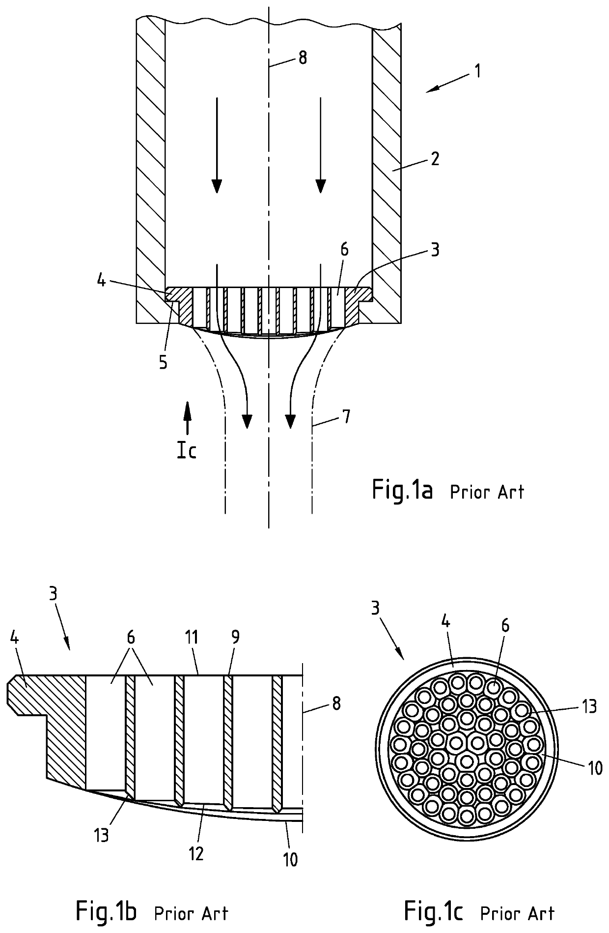
[0048]In FIG. 1 a filling nozzle 1 known from the prior art is illustrated in cross-section. The filling nozzle 1 comprises a body 2 and a plate 3 for shaping the flow. The plate 3 can be inserted exchangeably into the body 2, by a circumferential flange 4, which is provided on the plate 3, being placed onto a projection 5 which is provided on the body 2. The plate 3 has several holes 6 which permit a through-flow—illustrated diagrammatically in FIG. 1a by arrows—of the filling nozzle 1 with pourable products. After the exit from the filling nozzle 1, the pourable products form a jet 7, the outer contour of which is shown in FIG. 1. A center axis 8 runs centrally through the body 2 and the plate 3.

[0049]FIG. 1b shows an enlarged cut-out of the plate 3 of the filling nozzle 1 of FIG. 1a in cross-section. The regions of the plate 3 already described in connection with FIG. 1a are given corresponding reference numbers in FIG. 1b. The plate 3 has an upper side 9 for the entry of the pou...


PUM

PropertyMeasurementUnit
inclination angleaaaaaaaaaa

Abstract

A device is illustrated and described for altering the jet shape of pourable products, in particular of foodstuffs, including an entry region for the entry of the pourable products, an exit region for the exit of the pourable products, and several ducts for conveying the pourable products, wherein each duct has at least one inlet associated with the entry region and at least one outlet associated with the exit region. The use of this device for the filling of foodstuffs and a method for the production of this device are also illustrated and described. In order to achieve that the shape and the velocity profile of the filling jet can be adjusted simply and gently, it is proposed that at least one of the ducts is curved, at least in sections.

Description

CROSS-REFERENCE TO RELATED APPLICATIONS[0001]This application is the United States national phase of International Application No. PCT / EP2015 / 055020 filed Mar. 11, 2015, and claims priority to German Patent Application No. 10 2014 104 480.0 filed Mar. 31, 2014, the disclosures of which are hereby incorporated in their entirety by reference.BACKGROUND OF THE INVENTIONField of the Invention[0002]The invention relates to a device for altering the jet shape of pourable products, in particular of foodstuffs, comprising an entry region for the entry of the pourable products, an exit region for the exit of the pourable products, and several ducts for the conveying of the pourable products, wherein each duct has at least one inlet associated with the entry region and at least one outlet associated with the exit region.[0003]The invention additionally relates to the use of such a device for filling foodstuffs, in particular for the aseptic filling of foodstuffs.[0004]Finally, the invention r...

Claims


Application Information

Patent Timeline
Patent Type & Authority Patents(United States)
IPC IPC(8): B65B39/00B65B3/22B67C3/26B33Y10/00B33Y80/00B23K26/342B22F3/105B65B3/04B65B25/00B28B1/00C22C21/02C22C14/00B23K101/04B23K103/04B23K103/08B23K103/10B23K103/14B29K71/00
CPCB28B1/001C22C14/00C22C21/02B33Y10/00B65B3/04B23K26/342B67C3/2608B65B25/001B65B39/00B33Y80/00B65B3/22B22F3/1055B23K2103/08B23K2103/10B67C2003/2671B22F2302/45B23K2101/04B29K2071/00B65B2039/009B23K2103/04B23K2103/14B29C64/153Y02P10/25B22F10/28
Inventor HEUSER, RICHARDRABE, CHRISTIAN
Owner SIG TECH AG
Why Eureka
Try Eureka