
Apparatus and method for diversity transmission in a wireless communications system

a wireless communication system and antenna technology, applied in multiplex communication, orthogonal multiplex, channel coding adaptation, etc., can solve the problem that one sta may experience severe narrow-band interference, and achieve the effect of reducing narrow-band interference, improving per performance, and expanding transmission rang

Active Publication Date: 2020-02-04
PANASONIC INTELLECTUAL PROPERTY CORP OF AMERICA
View PDF9 Cites 0 Cited by
  • Summary
  • Abstract
  • Description
  • Claims
  • Application Information

AI Technical Summary

Benefits of technology

The present disclosure provides a solution to mitigate narrow-band interference and improve the performance of the Packet Error Rate (PER) for outdoor scenarios in the 802.11ax standard. This is achieved through efficient diversity transmission, which uses multiple antennas to transmit data fields of HE packets. By using this technique, a single STA can experience less severe narrow-band interference and the PER performance of the HE packet can be extended.

Problems solved by technology

Therefore one STA may experience severe narrow-band interference.

Method used


Image

  • Apparatus and method for diversity transmission in a wireless communications system
  • Apparatus and method for diversity transmission in a wireless communications system
  • Apparatus and method for diversity transmission in a wireless communications system

Examples


first embodiment

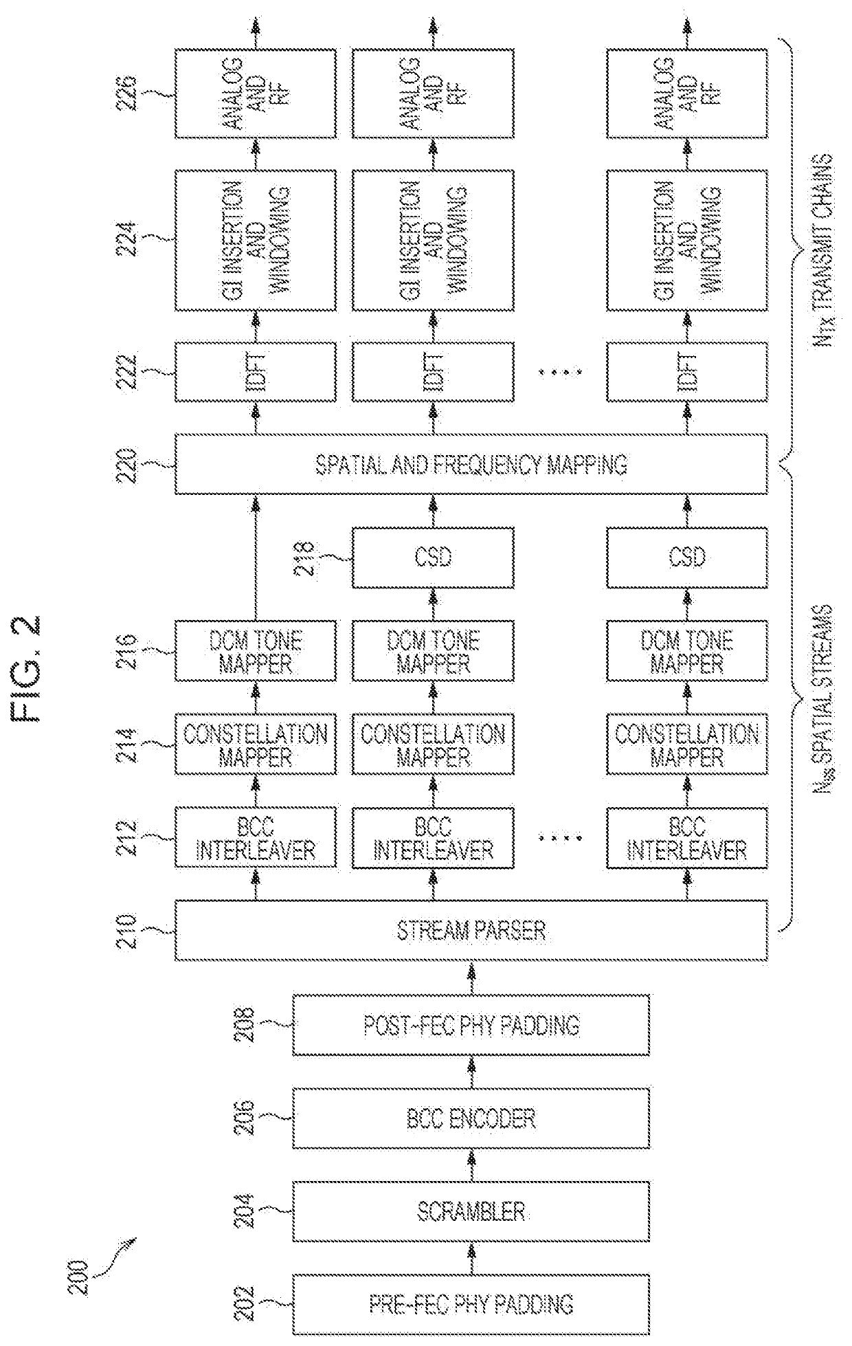
[0044]FIG. 5 illustrates an example method 500 for performing diversity transmission with any number of spatial streams according to a first embodiment of the present disclosure. The method 500 starts at step 502. At step 504, Nss spatial streams are paired into Np=pairs where

Np=floor(Nss / 2)  (1).

[0045]Notice that one of spatial streams is unpaired if Nss is an odd number.

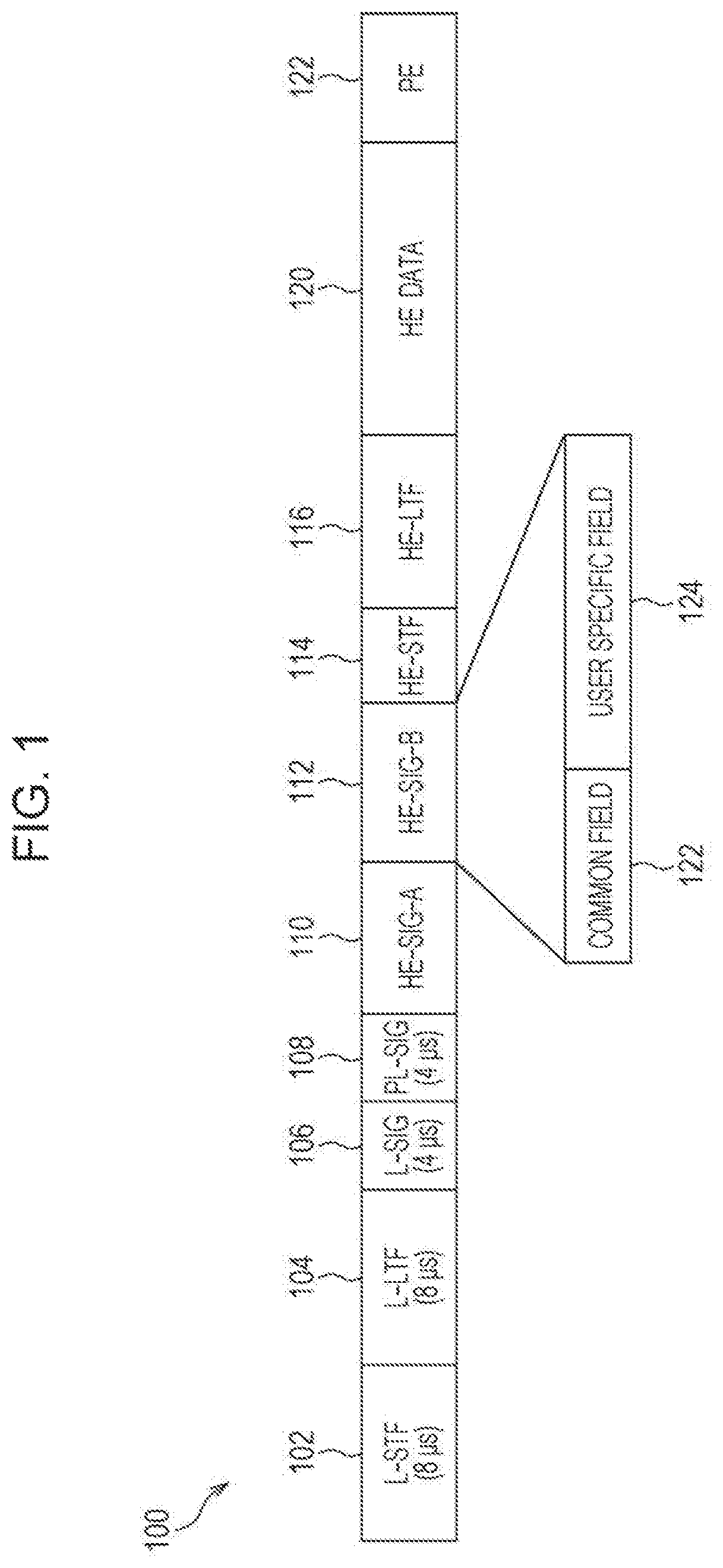
[0046]According to the first embodiment of the present disclosure, the method for pairing spatial streams can be configurable or predetermined. In case that there are several methods for pairing spatial streams are configurable, an additional signaling is required in the HE-SIG-A 110, the user-specific subfield of the HE-SIG-B 112 or the trigger frame to indicate the method that is actually used for pairing spatial streams used.

[0047]According to the first embodiment of the present disclosure, for open-loop (OL) MIMO transmission, spatial streams can be paired based on physical antenna configuration and mapping of ...

second embodiment

[0068]FIG. 8 illustrates an example method 800 for performing diversity transmission according to a second embodiment of the present disclosure. The method 800 starts at step 802. At step 804, if the number of spatial streams, Nss, is equal to 1, then the method 800 goes to step 806. Otherwise the method 800 goes to step 808.

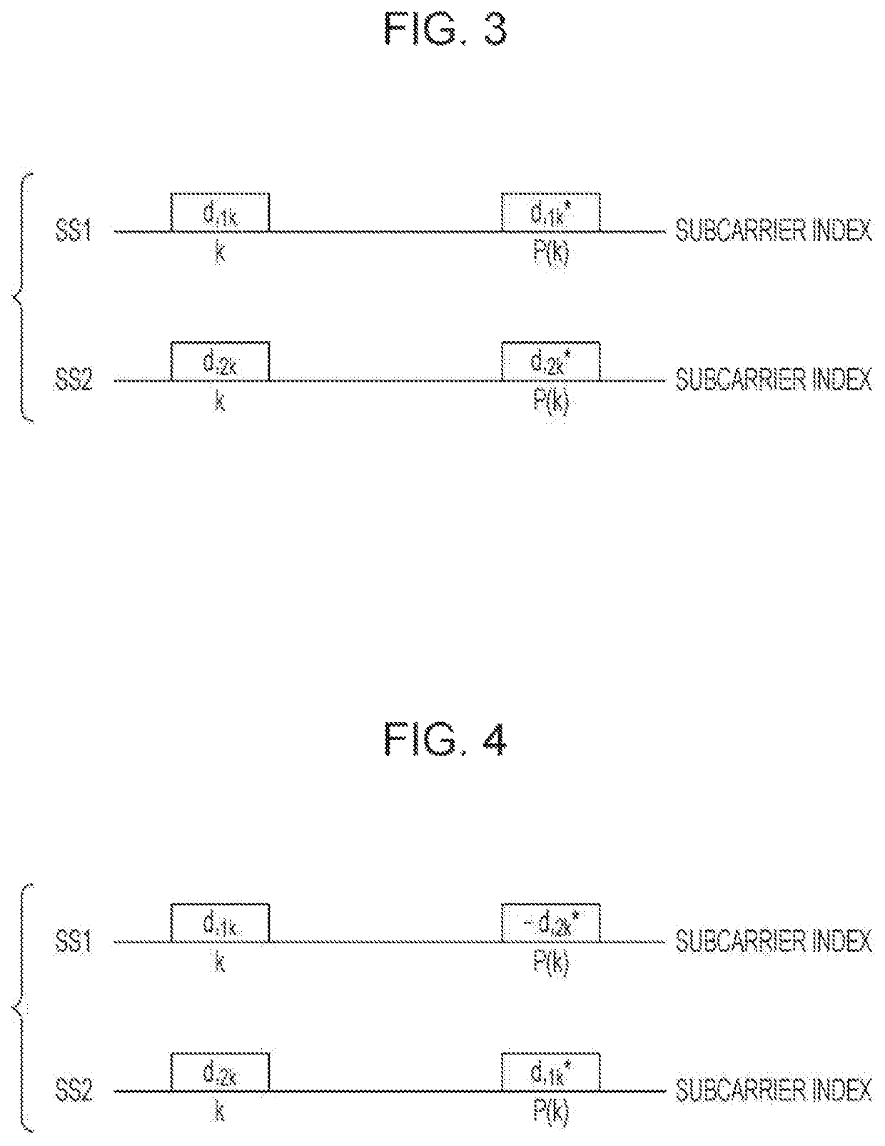
[0069]At step 806, the DCM as illustrated in FIG. 3 is applied to a single spatial stream. The method 800 stops at step 818. At step 808, if the number of spatial streams, Nss, is an even number, then the method 800 goes to step 810. Otherwise the method 800 goes to step 814.

[0070]At step 810, Nss spatial streams are grouped into Ng groups where

Ng=floor(Nss / 2)  (2).

[0071]Each of which comprises two spatial streams. At step 812, the SFDS as illustrated in FIG. 4 is applied to each of the Ng two-spatial-stream groups. The method 800 stops at step 818.

[0072]At step 814, Nss spatial streams are grouped into Ng groups where one of the Ng groups comprises three spatia...


PUM


Abstract

An transmission apparatus of the present disclosure comprises a transmission signal generator which, in operation, generates a transmission signal that includes a non-legacy preamble and a data field, the non-legacy preamble comprising a first field for indicating a number of spatial streams (Nss) in the data field and a second field for indicating one of a plurality of modulation and coding schemes (MCSs), wherein two or more frequency diversity transmission schemes are supported and each of the two or more frequency diversity transmission schemes is specified based on a value of the Nss; and a transmitter which, in operation, transmits the generated transmission signal.

Description

BACKGROUND1. Technical Field[0001]The present disclosure generally pertains to wireless communications and, more particularly, to an apparatus and a method for diversity transmission in a wireless communications system.2. Description of the Related Art[0002]The IEEE (Institute of Electrical and Electronics Engineers) 802.11 Working Group is developing 802.11ax HE (High Efficiency) WLAN (Wireless Local Area Network) air interface in order to achieve a very substantial increase in the real-world throughput achieved by users in high density scenarios. OFDMA (Orthogonal Frequency Division Multiple Access) multiuser transmission has been envisioned as one of the most important features in 802.11 lax. OFDMA is a multiple access scheme that performs multiple operations of data streams to and from the plurality of users over the time and frequency resources of the OFDM (Orthogonal Frequency Division Multiplexing) system.[0003]Frequency scheduling is generally performed for OFDMA multiuser t...

Claims


Application Information

Patent Timeline
Patent Type & Authority Patents(United States)
IPC IPC(8): H04L1/00H04L1/06H04B7/0413H04L27/26
CPCH04L27/2626H04B7/0413H04L1/0606H04L1/0003H04B7/068H04B7/0689H04L1/0009H04J11/0066H04L27/2601H04L27/2613H04L27/2634H04L5/0048H04L5/0025H04L27/26H04L1/00
Inventor HUANG, LEIURABE, YOSHIOCHITRAKAR, ROJAN
Owner PANASONIC INTELLECTUAL PROPERTY CORP OF AMERICA
Learn More