
Method and apparatus for transmitting a signal

a signal and transmission method technology, applied in the field of transmission methods, can solve the problems of large immobility of sensors, inability to fully optimize the cpm-ifdma approach with respect to remaining power fluctuations, etc., and achieve the effect of less transmission power, higher transmit range, and efficient maximum transmit power

Active Publication Date: 2016-06-23
FRAUNHOFER GESELLSCHAFT ZUR FOERDERUNG DER ANGEWANDTEN FORSCHUNG EV
View PDF44 Cites 17 Cited by
  • Summary
  • Abstract
  • Description
  • Claims
  • Application Information

AI Technical Summary

Benefits of technology

The patent allows for more efficient operation of transmitters by reducing the peak-to-average power ratio (PAPR) to about 0 dB, compared to LTE transmitters with a PAPR of about 5 dB. It also allows for more efficient use of a predefined maximum transmit power, which can result in higher transmit ranges without the need for more transmit power. These technical effects can be achieved by subjecting the temporary signal to a phase modulation while operating in the time domain.

Problems solved by technology

However, a majority of the sensors will be immobile.
IFDMA has not gained acceptance in LTE for several reasons, in particular the high pilot overhead necessitated for channel estimation.
In addition, the CPM-IFDMA approach seems to be not completely optimized with respect to the remaining power fluctuations.

Method used


Image

  • Method and apparatus for transmitting a signal
  • Method and apparatus for transmitting a signal
  • Method and apparatus for transmitting a signal

Examples


Embodiment Construction

[0035]Equal or equivalent elements or elements with equal or equivalent functionality are denoted in the following description by equal or equivalent reference numerals.

[0036]In the following description, a plurality of details is set forth to provide a more thorough explanation of embodiments of the present invention. However, it will be apparent to those skilled in the art that embodiments of the present invention may be practiced without these specific details. In other instances, well known structures and devices are shown in block diagram form rather than in detail in order to avoid obscuring embodiments of the present invention. In addition, features of the different embodiments described hereinafter may be combined with each other, unless specifically noted otherwise.

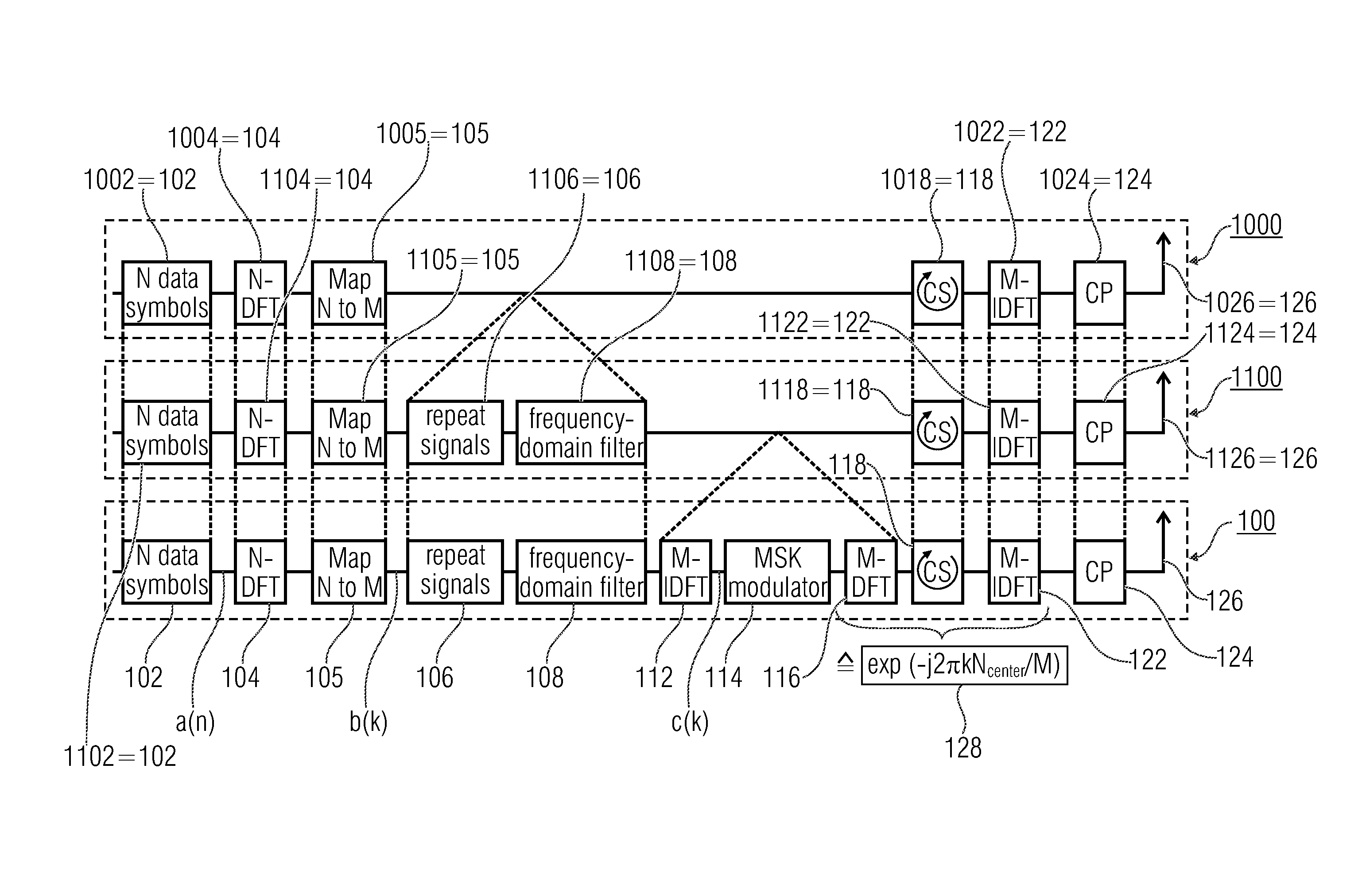
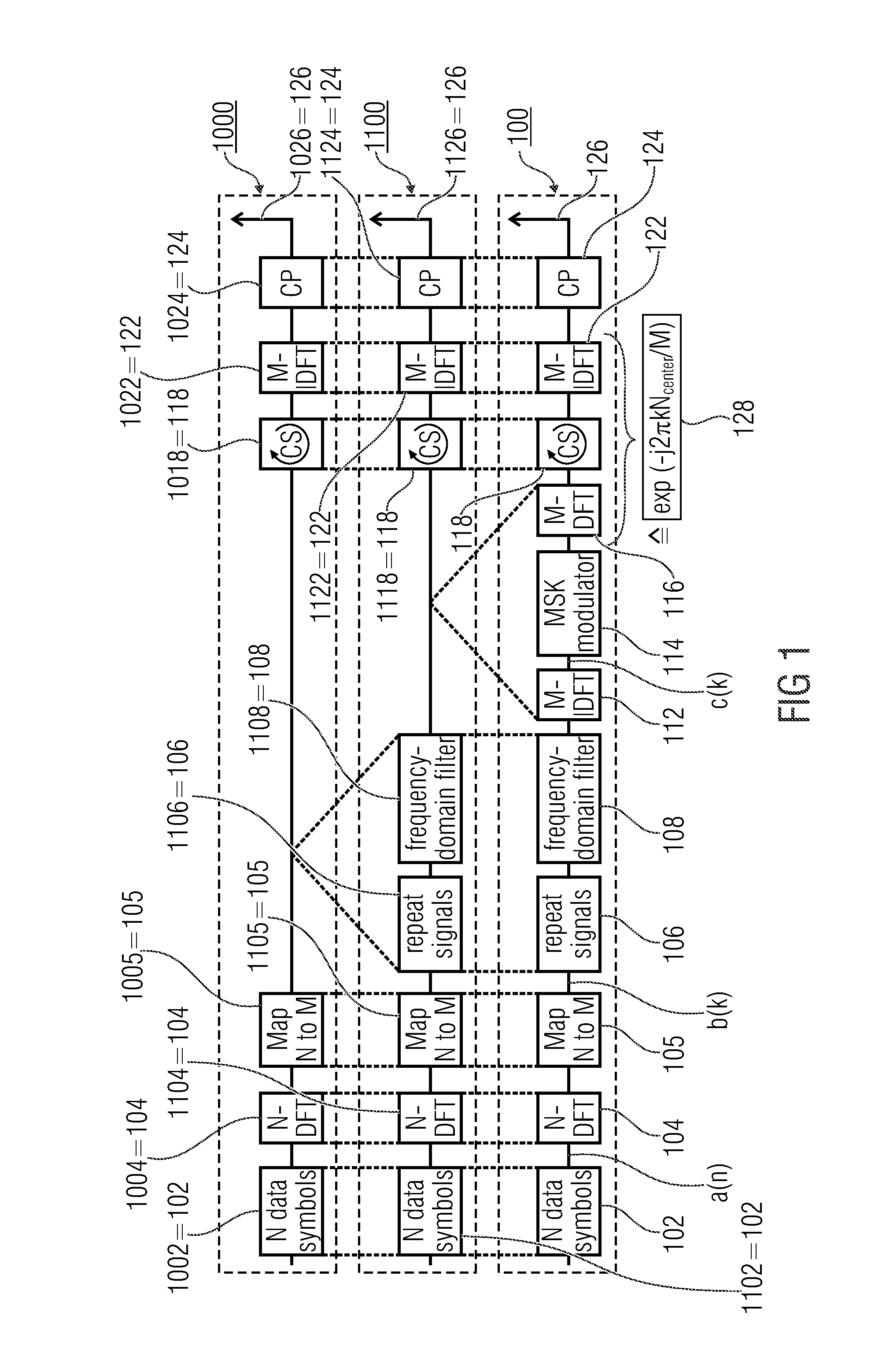
[0037]FIG. 1 shows a schematic block diagram of an advanced method 100 for transmitting a SC-FDMA signal. FIG. 1 also depicts a flowchart of a method 1000 which conforms to a method performed in LTE Standard Rele...


PUM


Abstract

A method for transmitting a signal is described, wherein the method has transforming a signal into a frequency domain to obtain a spectrum, forming a filtered spectrum according to a filter spectrum and occupying a set of subcarriers of a frequency domain representation of an Orthogonal Frequency Division Multiplex (OFDM) signal with the filtered spectrum. A temporary signal is obtained by transforming the frequency domain representation of the OFDM signal into a time domain. The temporary signal is subjected to a phase modulation.

Description

CROSS-REFERENCE TO RELATED APPLICATION[0001]This application is a continuation of copending International Application No. PCT / EP2013 / 068019, filed Aug. 30, 2013, which is incorporated herein in its entirety by this reference thereto.BACKGROUND OF THE INVENTION[0002]Embodiments of the present invention relate to a method for transmitting a signal. Further embodiments relate to a method for receiving a signal. Further embodiments of the present invention relate to an apparatus for transmitting a signal. Further embodiments of the present invention relate to an apparatus for receiving a signal.[0003]In the field of multiple access algorithms via so-called shared-media channels the so-called Single-Carrier Frequency-Division Multiple Access (SC-FDMA) has gained acceptance in mobile communications in the Long Term Evolution (LTE) for the uplink from the terminals to the base station. This method provides a number of advantages, including: a high spectral efficiency, a highly flexible ass...

Claims


Application Information

Patent Timeline
Patent Type & Authority Applications(United States)
IPC IPC(8): H04L27/26H04W72/04
CPCH04W72/0453H04L27/2643H04L25/03828H04L27/2621H04L27/2636H04L27/2644H04L27/26526H04L27/26536H04L27/2649
Inventor JUNGNICKEL, VOLKERGROBE, LIANE
Owner FRAUNHOFER GESELLSCHAFT ZUR FOERDERUNG DER ANGEWANDTEN FORSCHUNG EV
Learn More