
Calibration of inverting amplifier based impedance analyzers

an impedance analyzer and inverter technology, applied in the field of electromechanical measurement, can solve the problems of sensor vulnerability to inaccurate measures, affecting measurement performance, and affecting the ideality of the op amp b>24/b>, and its ability to maintain a virtual ground, and the effect of affecting the ability to measure the effect of the impedan

Active Publication Date: 2020-02-04
TEXAS INSTR INC
View PDF14 Cites 2 Cited by
  • Summary
  • Abstract
  • Description
  • Claims
  • Application Information

AI Technical Summary

Benefits of technology

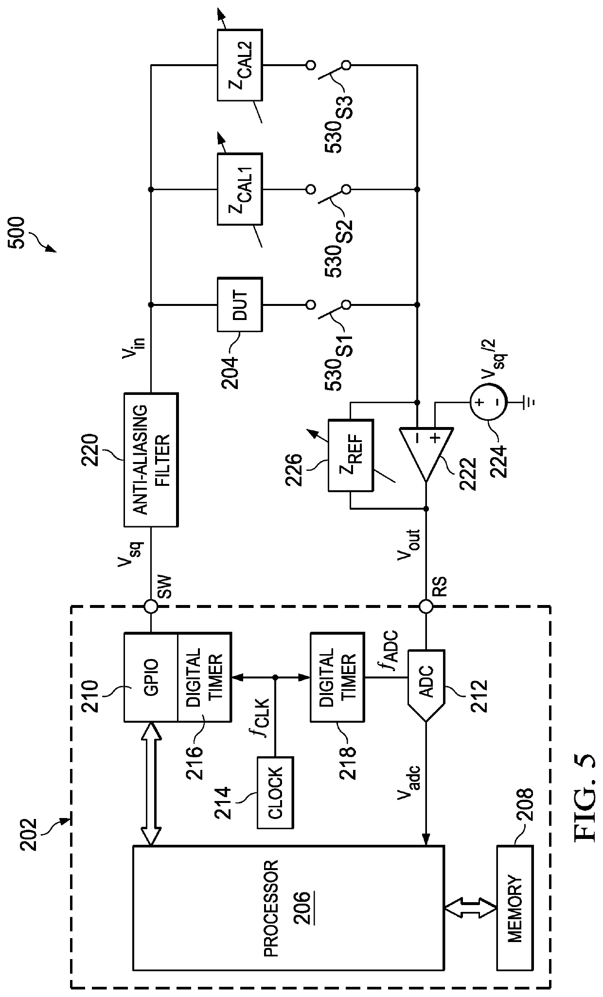
The patent describes a circuit that measures the impedance of a device under test (DUT). It includes a circuit that generates a stimulus wave, an amplifier circuit that presents a response signal from the DUT, a switching circuit that selectively connects either the stimulus wave or a calibration impedance to the amplifier, and a processor circuit that samples the response signal. The processor circuit iterates through three variations by connecting the stimulus wave to the calibration impedance and the DUT, and samples three signals responsive to the conversation. The processor then provides a measure of the impedance of the DUT based on the samples. The invention aims to improve the accuracy and reliability of impedance measurements for testing devices.

Problems solved by technology

However, as detailed below, such sensors may be vulnerable to inaccurate measures, for example at higher frequencies and / or with the inclusion of a lower cost operational amplifier as part of the sensor, where such attributes provide non-idealities which therefore can affect measurement performance.
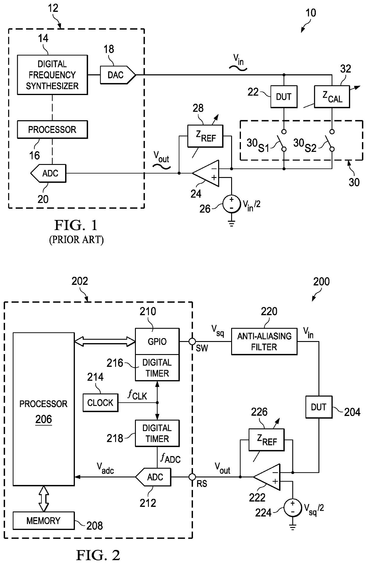
However, the idealities of the op amp 24, and its ability to maintain a virtual ground, are likely to be affected at higher frequencies, such as beyond 100 KHz.
One manner of attempting to address these factors is to implement a more expensive op amp, but such an approach may be cost prohibitive and also may still be somewhat vulnerable to these changes, again therefore diminishing the accuracy of DUT impedance measure that arises from the analyzer 10 which is relying on the op amp.

Method used


Image

  • Calibration of inverting amplifier based impedance analyzers
  • Calibration of inverting amplifier based impedance analyzers
  • Calibration of inverting amplifier based impedance analyzers

Examples


Embodiment Construction

[0021]FIG. 1 was discussed in the Background Of The Invention section of this document and the reader is assumed familiar with the aspects of that discussion.

[0022]Also by way of introduction, one or more preferred embodiments are described in this specification as implemented into a microcontroller or other large scale integrated circuit, as it is contemplated that the implementation of these embodiments will be particularly advantageous in such contexts. However, it is also contemplated that preferred embodiment concepts may be beneficially applied to other applications that carry out the measurement or analysis of an electrical impedance. Accordingly, it is to be understood that the following description is provided by way of example only, and is not intended to limit the true inventive scope as claimed.

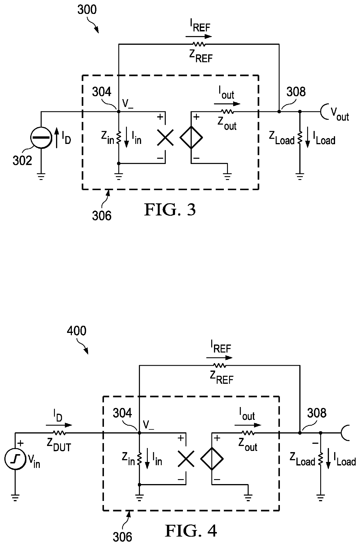
[0023]FIG. 2 illustrates, in part, a microcontroller-based impedance analyzer 200 constructed according to a preferred embodiment, where as detailed later additional calibration a...


PUM


Abstract

A circuit for measuring an impedance of a device under test (DUT). The circuit includes: (i) circuitry for generating a stimulus wave at a stimulus frequency; (ii) an amplifier circuit coupled to the DUT to present a response signal from the DUT in response to the stimulus wave; (iii) switching circuitry for selectively coupling, between the stimulus wave and an input to the amplifier, either the DUT, a first calibration impedance, or a second calibration impedance. With the switching functionality, calibrations are performed so to provide a measure of impedance of the DUT in response to the plural calibrations.

Description

CROSS-REFERENCES TO RELATED APPLICATIONS[0001]This application claims priority, under 35 U.S.C. § 119(e), of Provisional Application No. 62 / 301,818 filed Mar. 1, 2016 and incorporated herein by this reference.[0002]This application is related to U.S. patent application Ser. No. 15 / 344,565, entitled “Impedance Analyzer Using Square Wave Stimuli,” filed Nov. 6, 2016, which is hereby incorporated herein by this reference.STATEMENT REGARDING FEDERALLY SPONSORED RESEARCH OR DEVELOPMENT[0003]Not Applicable.BACKGROUND OF THE INVENTION[0004]The preferred embodiments relate to electronic measurement and are more specifically directed to devices and methods of calibrating to compensate for non-idealities so as to better measure impedance of a circuit element.[0005]As fundamental in the art, the electrical impedance of an electrical circuit or circuit component is the opposition to current that the circuit or component presents to an applied voltage. In general, impedance is a complex quantity...

Claims


Application Information

Patent Timeline
Patent Type & Authority Patents(United States)
IPC IPC(8): G01R35/00G01R27/02
CPCG01R35/005G01R27/14
Inventor SESTOK, IV, CHARLES KASIMER
Owner TEXAS INSTR INC
Learn More