Eureka AIR delivers breakthrough ideas for toughest innovation challenges, trusted by R&D personnel around the world.

Current sensor for measuring an alternating current

a current sensor and alternating current technology, applied in the direction of voltage/current isolation, measurement devices, instruments, etc., can solve the problems of low measuring sensitivity of rogowski coil obtained with printed circuit technology, high cost and difficult reproduction, and inability to meet the needs of industrial production of good quality rogowski coils by means of classical winding techniques

Active Publication Date: 2020-01-28
SOCOMEC
View PDF19 Cites 2 Cited by
  • Summary
  • Abstract
  • Description
  • Claims
  • Application Information

AI Technical Summary

Benefits of technology

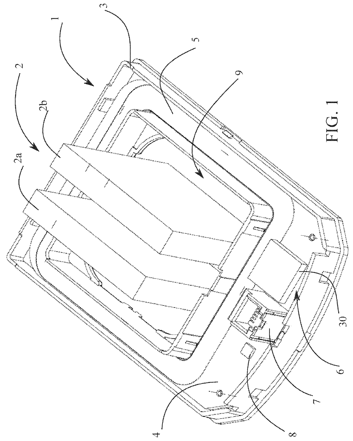
[0008]The present invention aims to overcome this problem by offering a new design of the Rogowski-type coils for a current sensor, these coils being made in the form of a printed circuit, having a substantially polygonal shape, whose measuring sensitivity is maximized while ensuring good immunity against the position variations of the primary conductor with respect to the current sensor, and a good immunity against the currents flowing through the neighboring primary conductors, comparable to those of circular coils with a similar technology, and offering a reduced size that allows installing the current sensors on primary conductors very close to each other, as well as ease of integration in any measuring appliance configuration.
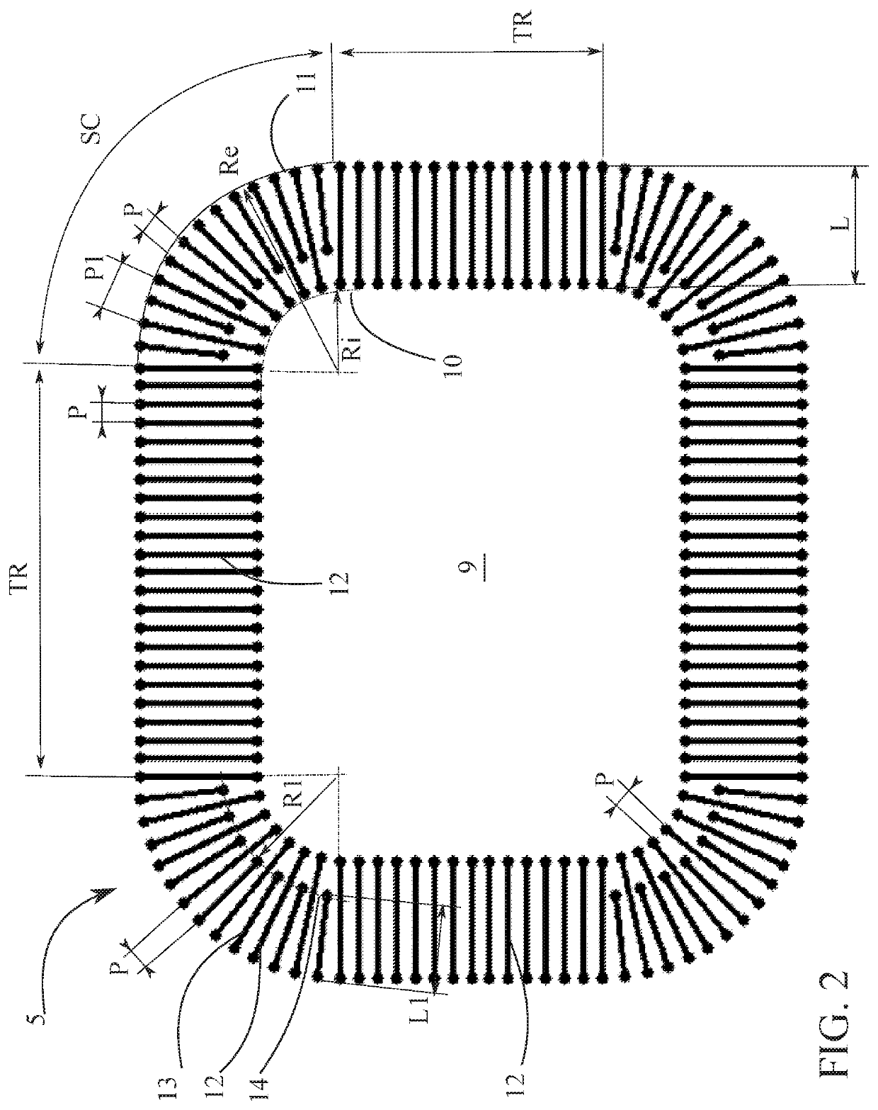
[0010]So, the regularity of spacing P between turns, on the interior periphery as well as on the exterior periphery of the electrical coil, and the regularity of the average turns density in the whole width of the electrical coil, as well in the rectilinear segments as in the circular sectors, allow both maximizing the measuring sensitivity of the measuring sensor and minimizing the sensitivity of the measuring sensor to the position of the primary conductor and to the presence of neighboring conductors.

Problems solved by technology

However, the industrial manufacture of good quality Rogowski coils by means of the classical winding techniques is very complex, expensive and difficult to reproduce, as these coils require a constant turns density per unit length and a constant turn cross-section.
However, the Rogowski coils obtained with this printed circuit technology have a low measuring sensitivity, for example in the order of 10 μV / A for a current to measure with a frequency of 50 Hz, as turns density is low, of the order of 1 to 1.2 turns per mm for the classical printed circuit technologies, and as the turns cannot be superimposed.
The use of polygonal coils, as those described for example in publications EP 1 923 709 and US 2014 / 0167786, presents winding regularity problems in the corners and affects coil quality.
Therefore, the use of circular coils leads to a size of the current sensor that is much larger than with rectangular coils, sometimes to such an extent that the installation of the current sensor becomes impossible because of the proximity of the primary conductors of the other phases.
But this solution is not optimal in terms of sensitivity.
Now the sensitivity of such a sensor is mainly determined by the turns density in its rectilinear segments, which in this case is insufficient, having a negative impact on measurement accuracy.
Therefore these existing solutions are not satisfactory.

Method used


Image

  • Current sensor for measuring an alternating current
  • Current sensor for measuring an alternating current
  • Current sensor for measuring an alternating current

Examples


first embodiment

[0011]In a first embodiment variant, the electrical coil can comprise, in its circular sectors, first additional turns with a width extending from said exterior arc towards respectively a first intermediate arc located between said interior arc and said exterior arc.

second embodiment

[0012]In a second embodiment variant, the electrical coil can comprise, in its circular sectors, first additional turns and second additional turns with different respective widths extending from said exterior arc towards respectively a first intermediate arc and a second intermediate arc located between said interior arc and said exterior arc.

[0013]In a preferred embodiment of the invention, the electrical coil is made in the form of a printed circuit comprising at least a first conductive layer and a second conductive layer, superimposed on each other, separated from each other by an insulating core of a substrate of said electronic board, said first and second conductive layers being connected to each other by means of connecting holes passing through said substrate to form the turns of said electrical coil.

[0014]The current sensor can comprise a return conductor having a flat surface substantially equal to that of said electrical coil to cancel interference fields, said return c...


PUM


Abstract

A current sensor provided with an electrical coil (5) made in the form of a printed circuit. Its closed contour is inscribed within a rectangle delimiting a through window (9) for passing a primary conductor (2). It comprises four rectilinear segments (TR) connected two by two by a circular sector (SC), delimited by an interior arc (10) and an exterior arc (11). It comprises, in its circular sectors (SC), additional turns (13), which extend from exterior arc (11) towards an intermediate arc (14) located between interior arc (10) and exterior arc (11). They are inserted between the main turns (12) in such a way that the spacing between two consecutive turns (12, 13) on the exterior arc (11) is equal to spacing (P) of the main turns (12) in rectilinear segments (TR) and that the average turns density is almost constant in electrical coil (5).

Description

TECHNICAL SCOPE[0001]The present invention relates to a current sensor for measuring an alternating current, said sensor comprising at least one electrical coil made in the form of a printed circuit provided on at least one electronic board, an electronic unit for conditioning the signal of said electrical coil and an electrical terminal block, said electrical coil having a closed contour inscribed within a polygon and delimiting in its center a through window for an electrical conductor crossed by the alternating current to be measured, this conductor being called primary conductor, said electrical coil comprising N rectilinear segments of width L and N circular sectors of the same width L delimited each by an interior arc of interior radius Ri and an exterior arc of exterior radius Re, said rectilinear segments being connected two by two by a circular sector, said rectilinear segments being made of turns separated from each other by a constant spacing P, and said circular sectors ...

Claims


Application Information

Patent Timeline
Patent Type & Authority Patents(United States)
IPC IPC(8): G01R15/18
CPCG01R15/181
Inventor KERN, CHRISTIAN
Owner SOCOMEC
Why Eureka
Eureka Blog
Learn More