
Systems and methods for predictive diagnostics for mechanical systems

a predictive diagnostic and mechanical system technology, applied in the field of mechanical seal systems, can solve the problems of mechanical seal failure, excessive wear of the seal, and collapse of the thin film of lubricant, and achieve the effect of improving reliability and speed

Active Publication Date: 2020-01-28
JOHN CRANK UK
View PDF63 Cites 9 Cited by
  • Summary
  • Abstract
  • Description
  • Claims
  • Application Information

AI Technical Summary

Benefits of technology

This patent presents an invention that can monitor mechanical seall systems automatically, which will make them more reliable and faster. The invention includes multiple failure mode logic modules that can diagnose specific types of mechanical failures. These modules can be activated based on the likelihood of the failure occurring. This technology eliminates the need for human operators to constantly monitor the seal system, which can improve its efficiency and save time.

Problems solved by technology

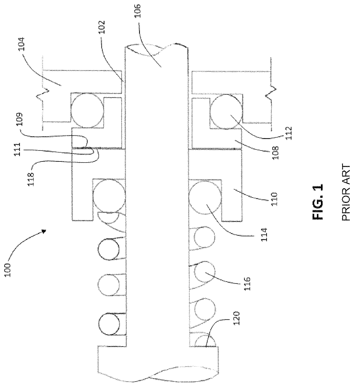
Excessive wear of the seal faces 109, 111 ultimately leads to failure of the mechanical seal 100.
Some of these conditions include misinstallation of seal components or improper seal selection, the seal faces opening during operation as a result of axial misalignment or improper loading, flashing (liquid to vapor transition that causes pulsating leakage and chatter of the seal), cavitation, or environmental conditions which can lead to a collapse of the thin film of lubricant.
Moreover, unexpected catastrophic equipment failure can result in injury to personnel.
Fortunately, in many cases the mechanical seal system will begin to show signs of distress in advance of a catastrophic failure, and in some cases indicate the remaining useful life of the components.
Conventional equipment monitoring is most often affected by a person who periodically visits the equipment, to make observations of noise and leaks, and take vibration readings with an accelerometer.
One problem with this procedure is the time and labor costs involved.
Another problem is the fact that the equipment is not constantly monitored, thereby enabling acute conditions, such as flashing, cavitation, and the negative effects of certain environmental conditions to occur without warning.
Such systems are particularly useful in applications where the equipment to be monitored is in a hazardous location or access to such equipment is generally impeded.
Such advanced monitoring systems can provide limited amounts of control of the mechanical seal, seal support system or other components, in response to the monitored conditions.
Unfortunately, the information provided by the individual sensors of an advanced monitoring system in isolation has in some cases proved insufficient to make conclusive determinations about the overall health of the mechanical seal system.
Complex mechanical seal systems are known to experience failures for multiple interrelated reasons.
Human operators have the advantage of being able to reason in the abstract and potentially pull information from their experience, but a human operator's effectiveness can be hampered by their inability to digest large amounts of sensor data.
For example, in some situations, relevant data may be inadvertently ignored by the human operator, resulting in an improper diagnosis.
In other situations, a delay in making a decision about the health of the mechanical seal system may lead to a scenario in which it is no longer possible to avoid an impending failure, whereas had the decision been made earlier, corrective actions could have been taken to avoid the failure.
Moreover, the cost of installing and operating such mechanical seal systems can be prohibitive.
Second, the operator of the advanced monitoring system must have the requisite knowledge in order to properly diagnose potential failures, which typically requires higher wages.

Method used


Image

  • Systems and methods for predictive diagnostics for mechanical systems
  • Systems and methods for predictive diagnostics for mechanical systems
  • Systems and methods for predictive diagnostics for mechanical systems

Examples


Embodiment Construction

[0062]Referring to FIG. 1, a mechanical seal 100 according to the prior art is depicted. Details of the mechanical seal 100 are described in the Background section above. In other embodiments, mechanical seal 100 can be an American Petroleum Industry (API) Standard 682 compliant seal. The American Petroleum Industry standards represent the oil and natural gas industry's collective wisdom on environmental protection, sound engineering and operating practices and safe, interchangeable equipment and materials. The API Standards Program is accredited by the American National Standards Institute (ANSI), and many of the API standards have been incorporated into state and federal regulations.

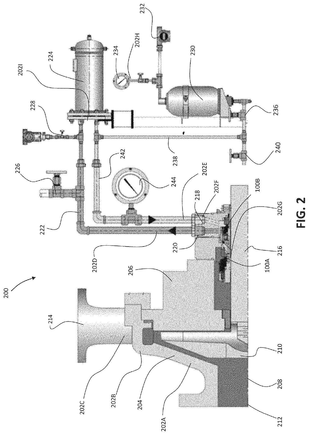
[0063]Referring to FIG. 2, a mechanical seal system 200 including mechanical seal 100 is depicted in accordance with an embodiment of the disclosure. In this embodiment, mechanical seal system 200 is depicted as an American Petroleum Industry (API) Standard 53B compliant system. Other contemplated mech...


PUM


Abstract

A predictive diagnostics system for monitoring mechanical seals. The system autonomously detects a loss of lubrication within a sliding seal interface of a mechanical seal, the system including a loss of lubrication failure mode logic module configured to monitor data sensed by one or more sensors and diagnose conditions relating to a loss of lubrication within the sliding seal interface, and a plurality of other failure mode logic modules configured to monitor data sensed by the one or more sensors and diagnose conditions relating to specific types of mechanical failures known to occur in mechanical seal systems, the loss of lubrication failure mode logic module configured to determine which of the plurality of other failure mode logic modules are activated during the diagnosis of conditions related to a loss of lubrication within the sliding seal interface.

Description

RELATED APPLICATIONS[0001]The present application claims the benefit of U.S. Provisional Application No. 62 / 298,814 filed Feb. 23, 2016, U.S. Provisional Application No. 62 / 298,839 filed Feb. 23, 2016, U.S. Provisional Application No. 62 / 298,848 filed Feb. 23, 2016, U.S. Provisional Application No. 62 / 298,851 filed Feb. 23, 2016, U.S. Provisional Application No. 62 / 302,458 filed Mar. 2, 2016, and U.S. Provisional Application No. 62 / 302,451 filed Mar. 2, 2016, each of which is incorporated herein by reference in its entirety.TECHNICAL FIELD[0002]The present disclosure relates generally to mechanical seal systems. More particularly, the present disclosure relates to a system configured to detect operating conditions, provide real-time health assessments and predictive diagnostics for mechanical seal systems.BACKGROUND[0003]A mechanical seal is a device configured to provide a sealing interface between a static housing and rotating shaft of a device, such as a pump, mixer or the like, ...

Claims


Application Information

Patent Timeline
Patent Type & Authority Patents(United States)
IPC IPC(8): G01N29/14G01M3/26G07C3/00
CPCG01N29/14G01M3/26G07C3/00F16J15/3492G01M13/005G01N29/326G01N29/48G01N2291/0226G01N2291/0258G01N29/4436
Inventor MECK, KLAUS-DIETERPARMAR, AMRATUNSWORTH, DAVID
Owner JOHN CRANK UK
Learn More