Decompression engine for executable microcontroller code

Active Publication Date: 2020-01-21
CEREMORPHIC INC
View PDF8 Cites 2 Cited by
  • Summary
  • Abstract
  • Description
  • Claims
  • Application Information

AI Technical Summary

Benefits of technology

The code compression engine identifies branch labels and places them on addressable boundaries, adjusting branch instructions to include an offset value to ensure the branch is to the desired address. This allows for efficient storage and retrieval of compressed code. The controller delivers subsequent decompressed symbols in sequential addresses, and passes non-sequential addresses through to the compressed image storage. The result is decompressed original instructions for sequential instructions or after a branch operation for efficiency in execution of those instructions. The technical effects include efficient storage and execution of compressed code.

Problems solved by technology

/ b>. If the compression ratio is 4:1, such that the compressed image is 25% of the size of the original uncompressed file, then the disadvantage of this approach is that RAM 206 must be four times the size of flash memory 204<
One problem of decoding compressed images is that the symbol boundaries from one compressed opcode to another are of variable length, so it is not possible to access a particular part of the compressed file in a granular manner to decompress a particular instruction without starting from an initial compression entry point and decompressing the successive values to maintain synchronization with the preceding symbols and retrieve the desired symbol for decompression into the desired opcode.
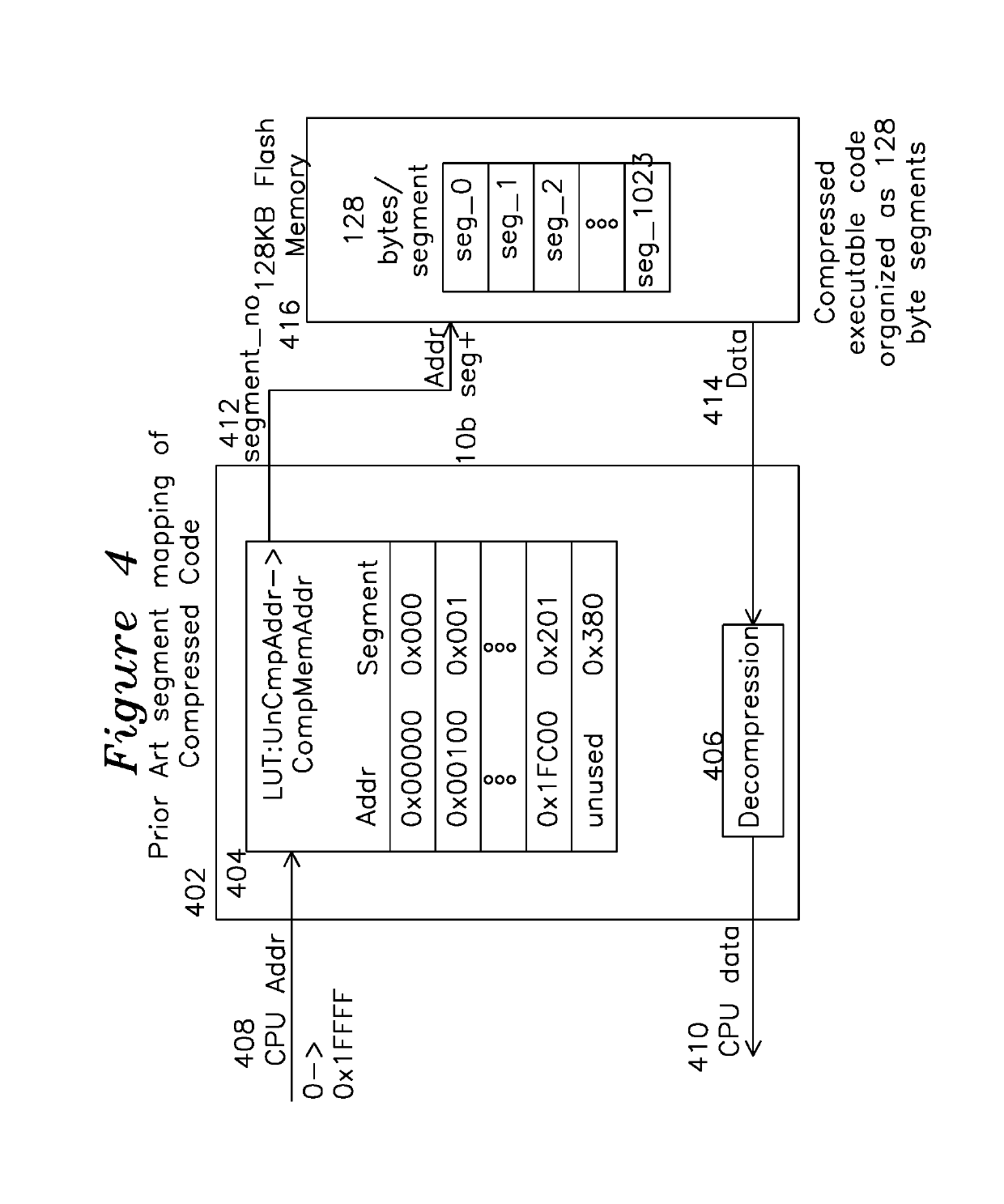
The memory requirements of the prior art system of FIG. 4 are reduced over the wholesale decompression of the image into Random Access Memory (RAM) of FIG. 2, but the use of multiple segments and look-up table 404 still requires an undesired level of overhead.
Another problem of decompressing an image into memory is that it increases the execution memory requirement.
For either the relative or absolute address target for next instruction execution, the problem remains that the compression methods of the prior art provide variable compression ratios on an instruction by instruction basis, so it is indeterminate as to what address to branch in the compressed code, since the compression of the corrected branch address into compressed code may result in different length than the uncorrected branch location, resulting in a non-converging branch address over iterations of compression attempts.

Method used


Image

  • Decompression engine for executable microcontroller code
  • Decompression engine for executable microcontroller code
  • Decompression engine for executable microcontroller code

Examples


Embodiment Construction

[0032]The system shown in FIG. 3 provides a decompression engine 302 coupled to CPU 312, which requests an address 304, the decompression engine 302 converts this to an address 306, receives associated data 308, decompresses it, and passes it to the CPU as CPU data 310. The memory 314 may be flash memory in one example of the invention. Note that in the present patent application, references numbers to a particular structure are used to invoke the function of the same structure in other figures.

[0033]FIG. 5 shows a compressed code controller 502 coupled to memory 528, which in practice is a single memory device, but is shown as two blocks comprising compressed instructions 531 (having irregular boundaries between compressed instructions) and 32 bit dictionary entries 532 with fixed width entries for clarity. Other variations of memory width may be practiced, the present 32 bit examples are provided only for understanding the invention. A CPU address 516 is applied to compressed inst...


PUM


Abstract

A code decompression engine reads compressed code from a memory containing a compressed code part and a dictionary part. The compressed code part contains a series of instructions being either an uncompressed instruction preceded by an uncompressed code bit, or a compressed instruction having a compressed code bit followed by a number of segments field followed by segments, followed by a directory index indication a directory location to read. Each segment consists of a mask type, a mask offset, and a mask.

Description

FIELD OF THE INVENTION[0001]The present invention relates to a code decompression apparatus and method. In particular, the present invention provides a decompression engine which receives requests for executable processor code and data by providing an input address from an embedded processor and returning the executable code or data of the requested address, while maintaining the stored code in a compressed form in local storage.BACKGROUND OF THE INVENTION[0002]Lossless compression provides for significant reductions in the size of executable instructions stored in memory, also known as executable image files. Lossless compression techniques typically utilize an associative table which contains repeating bit patterns found in the file to be compressed, and which is accessed by bit patterns which reference the associative table. In this method, a file is compressed by analyzing for repeating binary patterns, and those patterns are added to a dictionary, and then the dictionary is ref...

Claims


Application Information

Patent Timeline
IPC IPC(8): H03M7/00G06F16/901H03M7/30G06F9/30G06F9/22
CPCG06F9/223G06F16/901G06F9/3005H03M7/3066H03M7/6005G06F9/30178H03M7/3084H03M7/702
Inventor KALLAM, SUBBA REDDYMUDULODU, SRIRAM
Owner CEREMORPHIC INC
Why Eureka
Try Eureka