
Image based method and system for building object model and application states comparison and graphic-based interoperability with an application

a building object and image technology, applied in the field of interoperability, can solve the problems of affecting the interoperability of computer applications, allowing the installation of certain applications and/or software components on these servers, and many applications contain components that are not accessible, so as to improve the technology of computer application interoperability and communication, improve the underlying functionality of the computer system, and improve the effect of interoperability and communication

Active Publication Date: 2020-01-21
NICE LTD
View PDF21 Cites 0 Cited by
  • Summary
  • Abstract
  • Description
  • Claims
  • Application Information

AI Technical Summary

Benefits of technology

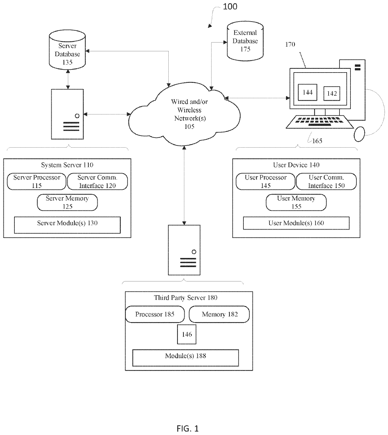
[0008]Some embodiments of the invention improve the underlying functionality of the computer systems on which embodiments of the invention are executed by for example allowing different executing programs to communicate, integrate, operate together, or work together, or to more efficiently do so. Embodiments of the invention may improve the technology of computer application interoperability and communications. For example, embodiments may enable the development and use of run-time solutions for integration of an application with third party applications, such as applications running in remote environments having only visual representation of the UI on a client (e.g., a customer) desktop. Application communications independent of platform, operating system or standards, and based only on a visual representation, may be achieved. Some embodiments of the invention enhance functionality of applications instantiated on client devices in a server / client architecture, which may make it possible to avoid unnecessary installation, development, or configuration of software on remote servers and client devices, thus conserving memory and maximizing processing power on such servers and devices. Such enhancements may reduce total cost and development time for applications to be run in such environments.
[0009]Remote servers provided to customers by external information technology (TT) companies may include security policies and / or physical limitations (memory usage, speed requirements, etc.) which do not allow for installation of certain applications and / or software components on these servers. Some embodiments of the invention solve this problem by providing the functionality of such applications and / or software components without requiring actual installation on such servers, and / or requiring minimal installation on client systems, which may be more accessible to a third party than the server controlling the client application. Furthermore, many applications contain components that are not accessible via existing integration technologies. Some embodiments of the invention enable access to such components, which may lower time and effort of research and development to develop connectors to support these applications by providing an out-of-the-box solution for it. Embodiments may provide a simple way to adapt or connect two pre-existing software packages. Furthermore, some embodiments of the invention may function as a universal real-time connector which may be used with any application type. Such a universal real-time connector may be independent of the application platform (e.g., the desktop, server, etc.) and even independent of any operation system.

Problems solved by technology

Remote servers provided to customers by external information technology (TT) companies may include security policies and / or physical limitations (memory usage, speed requirements, etc.) which do not allow for installation of certain applications and / or software components on these servers.
Furthermore, many applications contain components that are not accessible via existing integration technologies.

Method used


Image

  • Image based method and system for building object model and application states comparison and graphic-based interoperability with an application
  • Image based method and system for building object model and application states comparison and graphic-based interoperability with an application
  • Image based method and system for building object model and application states comparison and graphic-based interoperability with an application

Examples


Embodiment Construction

[0025]In the following description, various aspects of the present invention will be described. For purposes of explanation, specific configurations and details are set forth in order to provide a thorough understanding of the present invention. However, it will also be apparent to one skilled in the art that the present invention may be practiced without the specific details presented herein. Furthermore, well known features may be omitted or simplified in order not to obscure the present invention.

[0026]Although embodiments of the invention are not limited in this regard, discussions utilizing terms such as, for example, “processing,”“computing,”“calculating,”“determining,”“establishing”, “analyzing”, “checking”, or the like, may refer to operation(s) and / or process(es) of a computer, a computing platform, a computing system, or other electronic computing device, that manipulates and / or transforms data represented as physical (e.g., electronic) quantities within the computer's reg...


PUM


Abstract

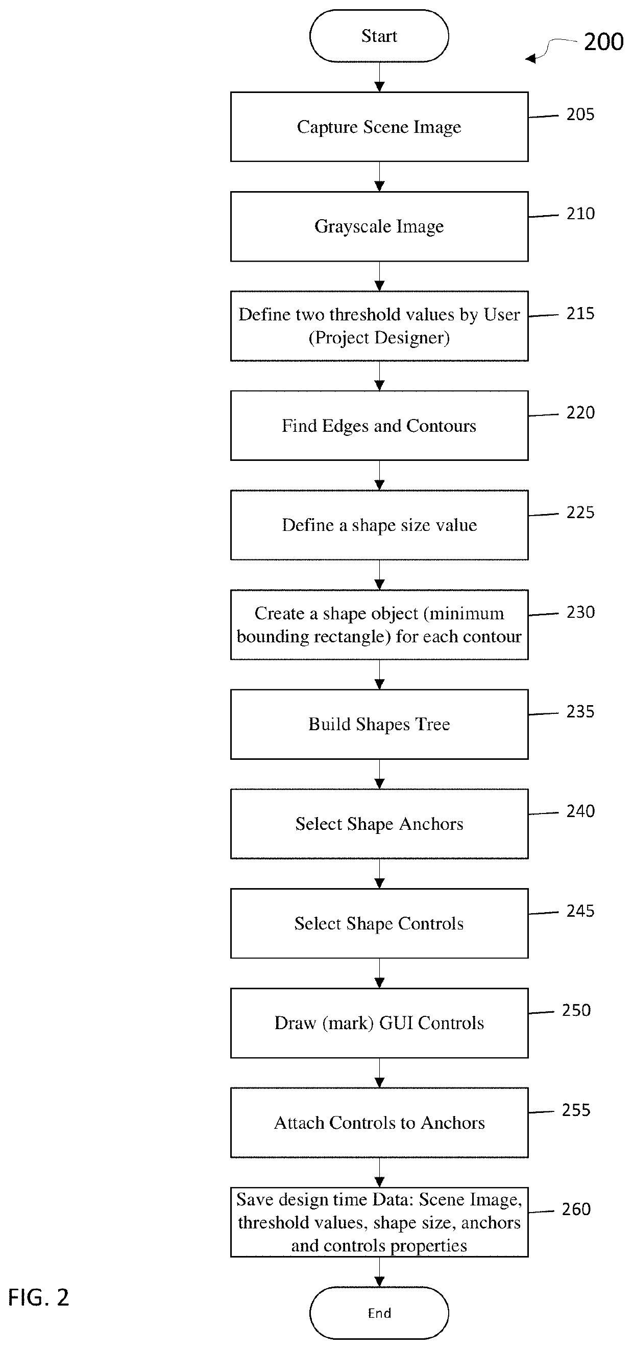
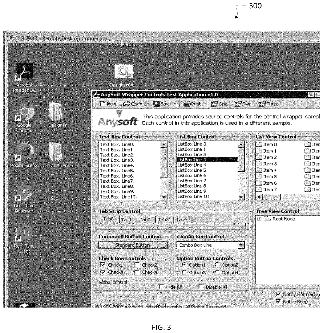
A system and method for enabling graphic-based interoperability between computer executed applications. A computer system operating as a client may display a graphical user interface (GUI) including control graphic items such as buttons, text boxes, etc. A process may examine the graphical image of the GUI to determine if there has been a change over time in the GUI as displayed which updates a control graphic item. If there has been a change over time in the GUI which updates a control graphic item, an action may be taken, for example updating properties of an object construct corresponding to the control graphic item, raising an event corresponding to an object construct corresponding to the control graphic item, or communicating an event to a process.

Description

RELATED APPLICATION DATA[0001]The present application is a continuation-in-part of prior U.S. application Ser. No. 15 / 416,484 entitled SYSTEM AND METHOD FOR ENABLING GRAPHIC-BASED INTEROPERABILITY WITH A RUN-TIME APPLICATION, filed on Jan. 26, 2017 and incorporated herein in its entirety.FIELD OF THE INVENTION[0002]The present invention is in the field of interoperability. In particular, the present invention is directed to systems and methods for enabling graphic-based interoperability between computer systems.BACKGROUND OF THE INVENTION[0003]Interoperability may be the ability of a computer system or application to work with other computer systems or applications, typically without special effort on the part of the users. Although many applications exist which can expose to another application or system an external graphical user interface (GUI) for interoperability via an application programming interface (API) or a software development kit (SDK) which allow interaction with the ...

Claims


Application Information

Patent Timeline
Patent Type & Authority Patents(United States)
IPC IPC(8): G06K9/00G06F8/38G06F8/65G06F9/451
CPCG06F9/451G06F8/38G06F8/65G06K9/00463G06K2209/03G06V30/414G06V2201/02
Inventor VAINDINER, ALEXANDERSHELEST, VITALYSTALOVEROV, YURI
Owner NICE LTD
Learn More