
Wind tunnel with an effective variable nozzle for testing various aerospace specific sensors and probes

a technology of variable nozzle and wind tunnel, which is applied in the direction of measurement devices, instruments, structural/machine measurement, etc., can solve the problems of increasing the labor cost of testing operation, wasting valuable time in idle testing equipment, and not allowing a smooth change in such areas, so as to achieve high flow rate and low flow rate

Active Publication Date: 2020-01-14
BIRCH BRIAN JEFFREY
View PDF3 Cites 3 Cited by
  • Summary
  • Abstract
  • Description
  • Claims
  • Application Information

AI Technical Summary

Benefits of technology

The apparatus described in this patent allows for continuous adjustment of the air flow by using a variable air heater, a pressure release value system, and a variable nozzle. The nozzle has an inverse cone assembly that includes an adjustment rod and a cone that is locked onto the rod. This design ensures precise control of the air flow exit area. The apparatus can be easily installed and maintained. The technical effect of this invention is to provide a precise and adjustable air flow that can be useful in various industrial applications.

Problems solved by technology

This not only adds considerably labor cost of the testing operation, but also, in elect, wastes valuable time in which the test equipment is idle.
Further, this type of wind tunnel precludes changing the effective cross-sectional area of the tunnel while it is in operation, but also does not allow a smooth change in such area, since the different replacement nozzles must of necessity differ appreciably from each other.

Method used


Image

  • Wind tunnel with an effective variable nozzle for testing various aerospace specific sensors and probes
  • Wind tunnel with an effective variable nozzle for testing various aerospace specific sensors and probes
  • Wind tunnel with an effective variable nozzle for testing various aerospace specific sensors and probes

Examples


Embodiment Construction

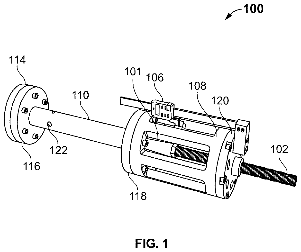
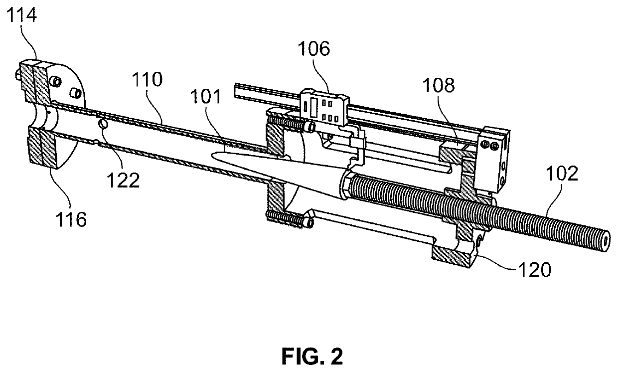
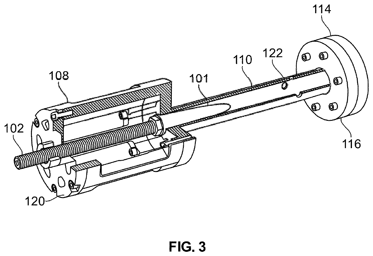
[0066]Referring to FIGS. 1 through 5, it is clear to see the primary components of the wind tunnel device or apparatus 100.

[0067]Referring specifically now to FIGS. 1 and 2, the cone / nozzle 101 is constructed of 304 Stainless Steel, connected and locked onto a course threaded adjustment rod 102, that is supported by a stainless end flange with a thickness that allows for minimal movement along the y and z axis through its x axis insertion distance.

[0068]The test tunnel portion 110 is connected to the adjustable device and the adapter flange 114 to the Hot Jet Test Rig 104 via Stainless Steel adapter flanges (116, 118), welded to each end of the test tunnel 110, also made of 304 Stainless Steel. 4 NPT ports 122 are tapped around the circumference of the test tunnel 110 near the entrance to reduce possible turbulence in that region caused by the cone 101 insertion distance for more accurate test probe measurements. The adjustable device housing is currently designed with 6061-T6 anodi...


PUM


Abstract

An apparatus for a unique wind tunnel useable for testing aerospace specific sensors and probes is presented. The apparatus utilizes an effective variable nozzle, allows testing of aerospace devices over a near infinite Mach and Reynolds numbers in subsonic flow. The variable nozzle allows for quick and easy adjustment over a minimum 1×10{circumflex over ( )}7 range of Reynolds number conditions from flow velocity of Mach 0.01 to 0.99. The optimal design of the apparatus allows for adaptation to different size test tunnels, using existing facilities to reduce cost, enabling various aerospace design applications. The apparatus of the present invention, provides a highly variable test environment in order to improve the development of advanced aerospace sensors, including benefits such as: development of flow sensors to prevent compressor stall; development of optical sensors to optimize turbine and compressor airflow; and, development of temperature sensors to increase efficiency of turbine engine operation.

Description

CROSS REFERENCE TO PRIOR APPLICATION[0001]This patent application claims the benefit of U.S. Provisional Application No. 62 / 423,816 filed on Nov. 18, 2016. The above provisional application is incorporated by reference herein in its entirety.FIELD OF THE INVENTION[0002]The present invention relates to an apparatus for a wind tunnel with an effective variable nozzle for testing of various aerospace specific sensors and probes, and, more particularly, to a variable nozzle for a wind tunnel device that allows for valid and effective aerospace testing at differing pressures, air flow rates and temperatures, even at subsonic speeds.BACKGROUND OF THE INVENTION[0003]The development of a wind tunnel with continuous control over the air flow parameters has been increasingly demanded as it helps in measuring aerodynamic forces, pressure distribution, or other aerodynamic-related characteristics. Since the air speed in a wind tunnel is determined completely by the geometry of the nozzle, it is...

Claims


Application Information

Patent Timeline
IPC IPC(8): G01M9/04G01M9/06
CPCG01M9/065G01M9/04
Inventor BIRCH, BRIAN JEFFREY
Owner BIRCH BRIAN JEFFREY
Learn More