Butterfly network on load data return

a network and load data technology, applied in the field of digital data processing, can solve problems such as limited capability, and achieve the effect of reducing the complexity of multiplexor control circuits

Active Publication Date: 2020-01-07
TEXAS INSTR INC
View PDF9 Cites 1 Cited by
  • Summary
  • Abstract
  • Description
  • Claims
  • Application Information

AI Technical Summary

Problems solved by technology

This limited capability is offset by the reduced complexity of the multiplexor control circuits.

Method used


Image

  • Butterfly network on load data return
  • Butterfly network on load data return
  • Butterfly network on load data return

Examples


Embodiment Construction

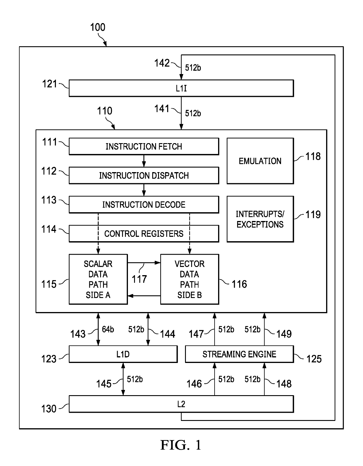
[0042]FIG. 1 illustrates a dual scalar / vector datapath processor according to a preferred embodiment of this invention. Processor 100 includes separate level one instruction cache (L1I) 121 and level one data cache (L1D) 123. Processor 100 includes a level two combined instruction / data cache (L2) 130 that holds both instructions and data. FIG. 1 illustrates connection between level one instruction cache 121 and level two combined instruction / data cache 130 (bus 142). FIG. 1 illustrates connection between level one data cache 123 and level two combined instruction / data cache 130 (bus 145). In the preferred embodiment of processor 100 level two combined instruction / data cache 130 stores both instructions to back up level one instruction cache 121 and data to back up level one data cache 123. In the preferred embodiment level two combined instruction / data cache 130 is further connected to higher level cache and / or main memory in a manner known in the art and not illustrated in FIG. 1. ...


PUM


Abstract

A method is shown that is operable to transform and align a plurality of fields from an input to an output data stream using a multilayer butterfly or inverse butterfly network. Many transformations are possible with such a network which may include separate control of each multiplexer. This invention supports a limited set of multiplexer control signals, which enables a similarly limited set of data transformations. This limited capability is offset by the reduced complexity of the multiplexor control circuits.

Description

TECHNICAL FIELD OF THE INVENTION[0001]The technical field of this invention is digital data processing and more specifically input to output data transformation.BACKGROUND OF THE INVENTION[0002]Modern digital signal processors (DSP) faces multiple challenges. Workloads continue to increase, requiring increasing bandwidth. Systems on a chip (SOC) continue to grow in size and complexity. Memory system latency severely impacts certain classes of algorithms. As transistors get smaller, memories and registers become less reliable. As software stacks get larger, the number of potential interactions and errors becomes larger.[0003]Memory bandwidth and scheduling are a problem for digital signal processors operating on real-time data. Digital signal processors operating on real-time data typically receive an input data stream, perform a filter function on the data stream (such as encoding or decoding) and output a transformed data stream. The system is called real-time because the applicati...

Claims


Application Information

Patent Timeline
Patent Type & Authority Patents(United States)
IPC IPC(8): H03M13/00G06F9/38H03M13/27
CPCG06F9/38H03M13/2789H03M13/6561H03M13/276G06F9/30032G06F9/383G06F9/30036G06F9/3891
Inventor BALASUBRAMANIAN, DHEERAZBICIAK, JOSEPHBUI, DUC QUANGANDERSON, TIMOTHY DAVID
Owner TEXAS INSTR INC
Why Eureka
Try Eureka