
Aircraft landing gear assembly

a technology for landing gears and aircraft, applied in mechanical equipment, transportation and packaging, drilling pipes, etc., can solve the problems of static pressure, unsuitable bearings for aircraft landing gear assemblies, etc., and achieve the effect of high strength

Active Publication Date: 2019-12-10
MESSIER DOWTY
View PDF12 Cites 0 Cited by
  • Summary
  • Abstract
  • Description
  • Claims
  • Application Information

AI Technical Summary

Benefits of technology

The patent describes a new type of polymer bearing that can withstand very high static pressures, making it suitable for use in aircraft landing gear assemblies. These bearings are much lighter than traditional bearings and require no grease channels, which can reduce weight. They are also flexible and can handle misalignment and high levels of stress. The bearing has a relatively self-lubricating layer made of epoxy containing particles of dry lubricant and a mix of PTFE fibres and carbon fibres. Its high strength layer is made of epoxy containing glass fibres. These bearings can be used to reduce the weight of landing gear assemblies and provide self-lubrication to the joint.

Problems solved by technology

These known bearings are therefore not suitable for use in aircraft landing gear assemblies, in which bearings can experience static pressures in excess of 400 MPa in view of shock loads.

Method used


Image

  • Aircraft landing gear assembly
  • Aircraft landing gear assembly
  • Aircraft landing gear assembly

Examples


Embodiment Construction

)

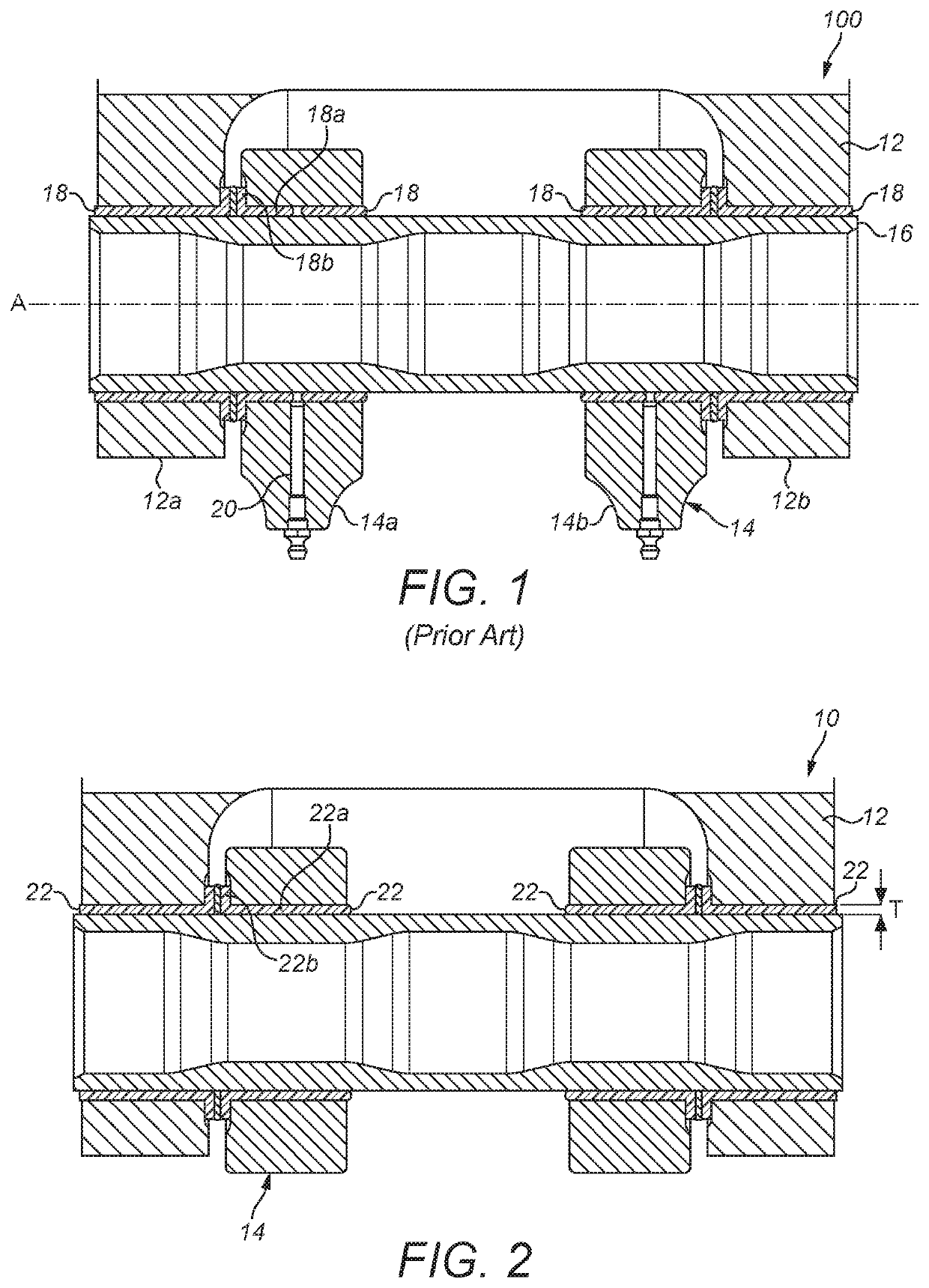
[0042]FIG. 1 shows part of a conventional landing gear assembly 100 in which a first structural member 12 is pivotally coupled to a second structural member 14 via a pin joint. The first structural member 12 terminates in a lug having a pair of arms 12a, 12b which define a space between them that is sized to receive first and second arms 14a, 14b of a lug defined at the end of the second structural member 14. Each arm 12a, 12b, 14a, 14b includes a hole such that when the lugs are aligned, a pin 16 can be received by each hole in order to pivotally couple the first structural member 12 to the second structural member 14. The first and second structural members 12, 14 can for example be main fitting attachment lugs, by which the main fitting is pivotally coupled to the airframe, links of a side stay, torque links, lock links, shortening links, bogie pivot pin, actuator attachments or the like.

[0043]Each lug hole is provided with a plain bearing 18 having a body 18a which extends gene...


PUM

PropertyMeasurementUnit
Static pressureaaaaaaaaaa
dynamic pressureaaaaaaaaaa
static pressureaaaaaaaaaa

Abstract

An aircraft landing gear assembly including structural members coupled via a coupling including a bearing. The bearing has a body defining a first bearing surface arranged to contact a first counter-face of the coupling. The first bearing surface is defined by a first tubular layer of fibre reinforced polymer of a first type having an axis and containing synthetic fibres of a first type wound around and along the axis of the bearing. The bearing body further has a second tubular layer of fibre reinforced polymer of a second type containing synthetic fibres of a second type wound around and along the axis of the bearing.

Description

[0001]This application claims the benefit of and priority to European Application EP 16164068.5, filed on Apr. 6, 2016, the contents of which are incorporated herein by reference.BACKGROUND OF THE INVENTION[0002]An aircraft landing gear assembly can include structural members coupled via a coupling or joint which includes one or more bearings. For example, members can be movably coupled via a pin joint. A pin joint will generally include a plurality of bearings, each being located between the pin and one of the structural members.[0003]Aircraft landing gear assembly joints can be designed to withstand static pressure in excess of 400 MPa. Static pressure results from first and second structural members acting on the joint while the aircraft is on the ground; for example, the lugs of side stay links acting on a common pin joint during aircraft taxiing, where the pin joint is subjected to multi-directional loading.[0004]Aircraft landing gear assembly joints can also be designed to wit...

Claims


Application Information

Patent Timeline
Patent Type & Authority Patents(United States)
IPC IPC(8): B64C25/10B65G23/04B65G39/06E21B19/22F16C13/00F16C33/20
CPCB64C25/10B65G39/06F16C33/203B65G23/04F16C13/006E21B19/22F16C33/04F16C2208/80F16C2208/04B64C25/34B64C25/36F16C33/205F16C33/208F16C2208/02F16C2326/43E21B2200/03
Inventor FOSTER, NICHOLASEVANS, SAM
Owner MESSIER DOWTY
Learn More