Image processing device, printing apparatus, image processing method, and non-transitory computer readable medium

a technology of image processing and printing equipment, applied in image data processing, printing, instruments, etc., can solve problems such as disordered characters, lines, and lines in the print image, and print apparatus that prints images

Active Publication Date: 2019-11-26
SEIKO EPSON CORP
View PDF6 Cites 0 Cited by
  • Summary
  • Abstract
  • Description
  • Claims
  • Application Information

AI Technical Summary

Benefits of technology

[0007]The first pixel region is a region where the dots (ink droplets) of the first ink forming the outline of the partial image contained in the print image contact the dots (ink droplets) of the second ink, or a region where the rate of such contact is high. In the present application example, print data is generated such that the application density of the second ink in the first pixel region is reduced. Thus, even in a case in which the dots (ink droplets) of the first ink and the dots (ink droplets) of the second ink contact each other, the degree to which the dots (ink droplets) of the first ink are affected by the dots (ink droplets) of the second ink is reduced (namely, the degree to which the dots (ink droplets) spread is reduced). This results in an even lower degree of the outline of the partial image contained in the print image being disordered.
[0036]In Application Example 12, among the halftone data corresponding to the second ink (in other words, the halftone data determining the formation positions and sizes of the second ink dots discharged by the printing apparatus), the determining converts the halftone data corresponding to the first pixel region to data that does not form dots. In other words, in the present application example, the print data is generated such that the printing apparatus is controlled so as not to discharge the second ink on the first pixel region (a region where the dots (ink droplets) of the first ink forming the outline of the partial image contained in the print image contact the dots (ink droplets) of the second ink, or a region where the rate of such contact is high). Thus, the dots (ink droplets) of the first ink forming the outline of the partial image contained in the print image will not contact the dots (ink droplets) of the second ink. Alternatively, the rate of such contact will be low. This results in an even lower degree of the outline of the partial image contained in the print image being disordered. Furthermore, the halftone data of the second ink corresponding to the pixels of the first pixel region is converted into data that does not form dots, or in other words, the data of the dot formation specifications for forming the dots where second is actually to be formed is converted into a specification whereby dots are not formed, and therefore it is possible to generate print data that provides more reliable and suitable effects.Application Example 13

Problems solved by technology

There are cases in which a printing apparatus that prints an image by discharging ink droplets onto a printing medium, such as an ink jet printer, may not achieve good printing quality depending on the specifications of the printing medium due to insufficient wet-spreading of the ink droplets (in other words, due to a dot diameter on the printing medium not being as large as expected).
However, in the method disclosed in JP-A-10-250216, although the print image is a good print image overall, there are cases where characters, line outline, etc. in the print image are disordered.
This results in an even lower degree of the outline of the partial image contained in the print image being disordered.

Method used


Image

  • Image processing device, printing apparatus, image processing method, and non-transitory computer readable medium
  • Image processing device, printing apparatus, image processing method, and non-transitory computer readable medium
  • Image processing device, printing apparatus, image processing method, and non-transitory computer readable medium

Examples


exemplary embodiment 1

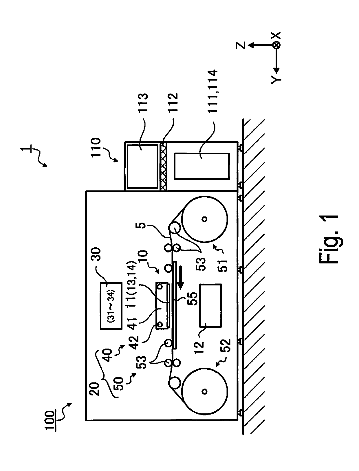
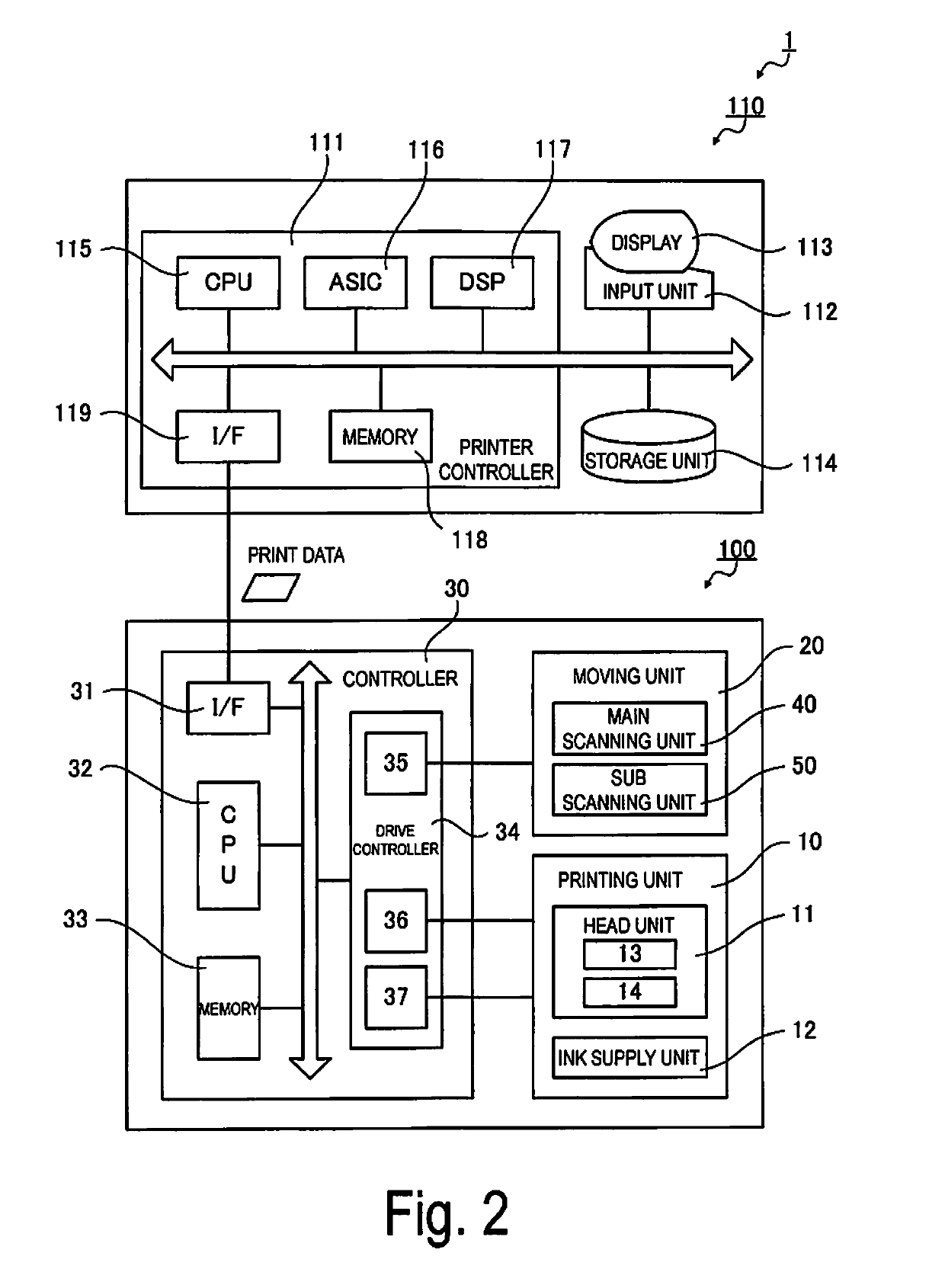
[0063]FIG. 1 is a front view illustrating the configuration of a printing apparatus 1 according to Exemplary Embodiment 1, and FIG. 2 is a block diagram of the configuration of the printing apparatus 1 according to Exemplary Embodiment 1. The printing apparatus 1 includes a printer 100, and an image processing device 110 that connects to the printer 100. The printer 100 is an ink jet printer that, based on print data received from the image processing device 110, prints a desired image on a roll paper 5, which is a long “printing medium” supplied while wound in a roll shape.

Basic Configuration of Image Processing Device

[0064]The image processing device 110 includes a printer controller 111, an input unit 112, a display 113, a storage unit 114, etc., and controls a print job that causes the printer 100 to print. The image processing device 110, in one example, is configured using a personal computer. The software operated by the image processing device 110 includes an ordinary image ...

modified example 1

[0121]In Exemplary Embodiment 1, it was described that among the halftone data corresponding to the clear ink (CL), the dot formation specification determining unit converts the halftone data corresponding to the first pixel region (the region including the pixel positions adjacent to the outer side of the edge pixels and pixel positions overlapping the edge pixels extracted by the edge extracting unit) into data that does not form dots. In other words, after the halftone data corresponding to the clear ink (CL) was generated, the print data was generated by a method where a working liquid mask process is performed so that the clear ink (CL) is not discharged on the first pixel region (refer to FIG. 14), but the disclosure is not limited to this method. For example, a method may be used whereby, before performing the halftone process, or in other words, after the color conversion process, a conversion is performed to set the gradation values of the clear ink (CL) in the image data t...

modified example 2

[0124]As illustrated in FIG. 13, in Exemplary Embodiment 1, it was described that print data is generated such that the printing apparatus 1 is controlled so as not to discharge clear ink (CL) in the first pixel region, but the disclosure is not limited to this configuration (method), and it is possible to use a configuration (method) that reduces the application density of the clear ink (CL) discharged on the first pixel region. Application density means the proportion of area with dots formed per unit area. In the image processing device 110 of Modified Example 2, the dot formation specification determining unit determines the dot formation specifications such that the application density of the clear ink (CL) discharged on the first pixel region including the pixel positions adjacent to the outer side of the edge pixels and pixel positions overlapping the edge pixels extracted by the edge extracting unit is less than the application density of the clear ink (CL) discharged on the...


PUM


Abstract

The disclosure includes an edge extracting unit configured to, based on image data corresponding to a print image, extract edge pixels forming an outline of a partial image, a dot formation specification determining unit configured to, based on the image data, determine dot formation specifications, and a print data generator configured to, based on the dot formation specifications, generate print data for causing execution of printing by a printing apparatus for printing the print image by discharging first ink on a printing medium and second ink that promotes spreading of the first ink on the printing medium to form the plurality of dots.

Description

BACKGROUND1. Technical Field[0001]The disclosure relates to an image processing device, a printing apparatus including the image processing device, an image processing method, and a non-transitory computer readable medium storing an image processing program for causing a computer to execute a process in accordance with the image processing method.2. Related Art[0002]There are cases in which a printing apparatus that prints an image by discharging ink droplets onto a printing medium, such as an ink jet printer, may not achieve good printing quality depending on the specifications of the printing medium due to insufficient wet-spreading of the ink droplets (in other words, due to a dot diameter on the printing medium not being as large as expected). As a method for improving compatibility between this type of printing medium and ink, there is a known method wherein colorless or light-colored clear ink for promoting predetermined wet-spreading or adhesion of ink droplets is applied to ...

Claims


Application Information

Patent Timeline
Patent Type & Authority Patents(United States)
IPC IPC(8): H04N1/00H04N1/50B41J2/21G06K9/46H04N1/52H04N1/58H04N1/54G06T7/12G06V10/44
CPCB41J2/2132H04N1/52G06T7/12H04N1/00188H04N1/00167H04N1/502H04N1/54G06K9/4604H04N1/58B41J2/2114G06V10/44
Inventor TANASE, KAZUYOSHIYAMADA, AKIRA
Owner SEIKO EPSON CORP
Why Eureka
Try Eureka