Screw, injection molding machine, and injection molding method
a technology of injection molding machine and screw, which is applied in the direction of coatings, etc., can solve the problems of inability to uniformly disperse the reinforcing fibers in the fiber reinforced resin, the cutting and the inability to achieve desired characteristics of the molded product, etc., to achieve the effect of eliminating the uneven distribution of the reinforcing fibers
- Summary
- Abstract
- Description
- Claims
- Application Information
AI Technical Summary
Benefits of technology
Problems solved by technology
Method used
Image
Examples
first embodiment
[First Embodiment]
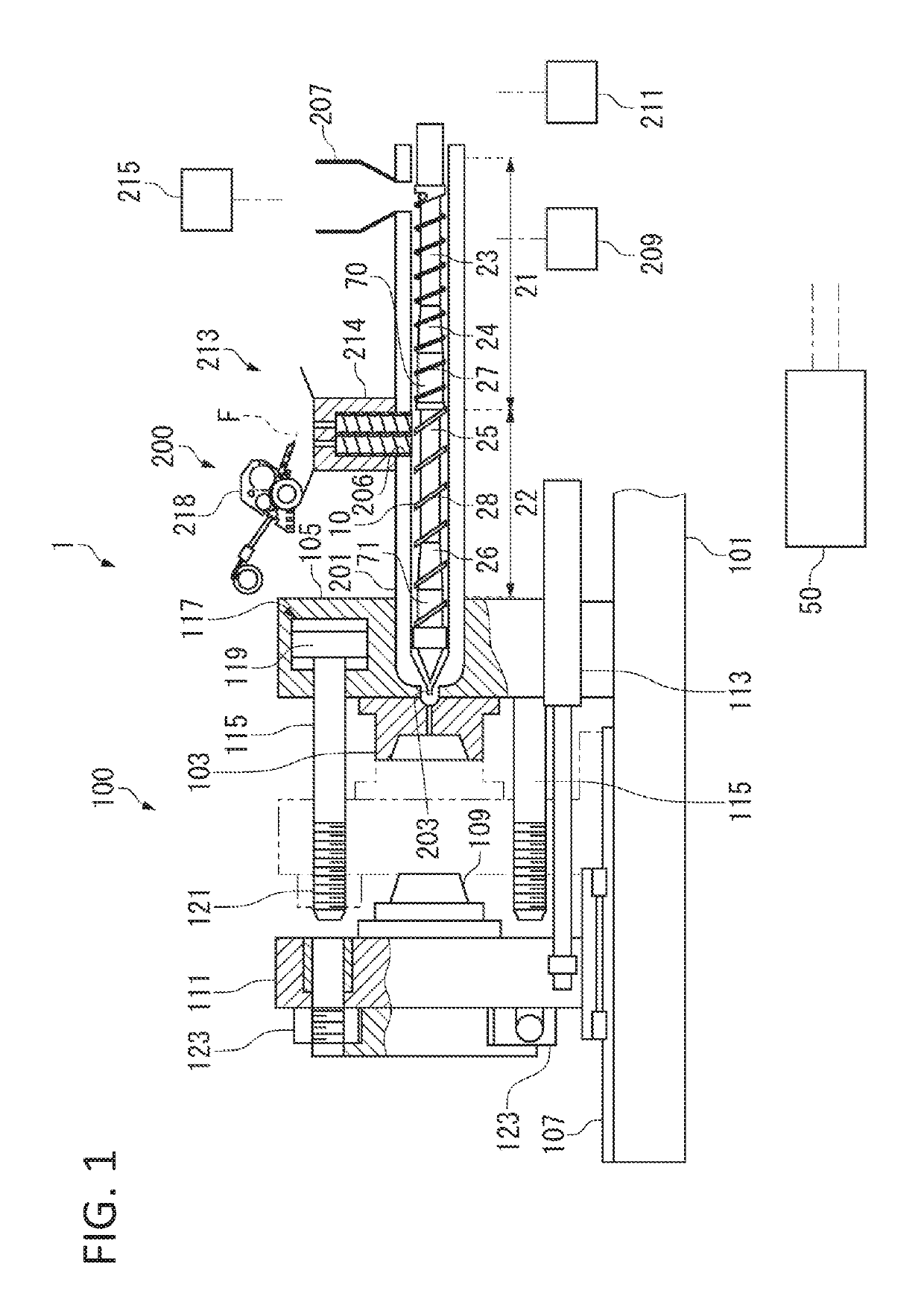
[0035]An injection molding machine 1 according to the embodiment, as shown in FIG. 1, includes: a mold clamping unit 100; a plasticizing unit 200; and a control unit 50 that controls operations of the units.
[0036]Hereinafter, outlines of a configuration and an operation of the mold clamping unit 100, and a configuration and an operation of the plasticizing unit 200 will be explained, and next, procedures of injection molding by the injection molding machine 1 will be explained.
[Configuration of Mold Clamping Unit]
[0037]The mold clamping unit 100 includes: a fixed die plate 105 that has been fixed on a base frame 101 and to which a fixed mold 103 has been attached; a movable die plate 111 that moves on a slide member 107, such as a rail and a slide plate in a left and right direction in FIG. 1 by actuating a hydraulic cylinder 113, and to which a movable mold 109 has been attached; and a plurality of tie bars 115 that couple the fixed die plate 105 with the movable ...
second embodiment
[Second Embodiment]
[0081]Although the screw with a single-thread flight, a so-called single-flight screw, has been explained in the first embodiment, double flight with a two-thread flight including the main flight and the sub-flight can be applied to the second stage 22. Hereinafter, a screw to which the double flight is applied will be explained as a second embodiment. The second embodiment includes a second-first mode in which the double flight is applied to a portion to which the reinforcing fibers F are fed, and a second-second mode in which the double flight is applied to a downstream region away from the portion to which the reinforcing fibers F are fed.
[0082]Note that regarding the second flight 28 in the first embodiment to be included in the main flight, hereinafter, the second flight 28 shall be read as the main flight 28, and the sub-flight is represented as a sub-flight 29. As for the other components, portions different from the first embodiment will be mainly explaine...
third embodiment
[Third Embodiment]
[0106]Although in the first embodiment and the second embodiment, examples have been explained where the resin passage in which the backflow of the melted resin raw material is generated is continuously provided in the predetermined range in the winding direction of the flight, the resin passage can be provided at a part of the winding direction of the flight in the present invention. Hereinafter, a screw in which the resin passage is applied to the part of the winding direction of the flight will be explained as a third embodiment.
[0107]Note that hereinafter, portions different from the first embodiment will be mainly explained, while citing the same symbols as in the first embodiment for the same components as in the first embodiment.
[0108]In a screw 10F according to the third embodiment, as shown in FIG. 7A, a notch 75 is provided in a part of the second flight 28, and a flight 28C of the upstream side and a flight 28D of the downstream side that are divided by ...
PUM
| Property | Measurement | Unit |
|---|---|---|
| pressure | aaaaa | aaaaa |
| size | aaaaa | aaaaa |
| size | aaaaa | aaaaa |
Abstract
Description
Claims
Application Information
 - R&D
- Intellectual Property
- Life Sciences
- Materials
- Tech Scout
- Unparalleled Data Quality
- Higher Quality Content
- 60% Fewer Hallucinations
Browse by: Latest US Patents, China's latest patents, Technical Efficacy Thesaurus, Application Domain, Technology Topic, Popular Technical Reports.
© 2025 PatSnap. All rights reserved.Legal|Privacy policy|Modern Slavery Act Transparency Statement|Sitemap|About US| Contact US: help@patsnap.com


