
Multi-core electric filling structure for large out light hole vertical cavity surface emitting semiconductor laser

A vertical cavity surface emission and semiconductor technology, which is applied in the direction of semiconductor lasers, lasers, laser components, etc., can solve the problems of strong light in the light hole, low light intensity, and excessive current in the light hole

Inactive Publication Date: 2009-01-28
CHANGCHUN UNIV OF SCI & TECH
View PDF10 Cites 0 Cited by
  • Summary
  • Abstract
  • Description
  • Claims
  • Application Information

AI Technical Summary

Problems solved by technology

For a vertical cavity surface-emitting semiconductor laser with a large light exit hole, the injection area of ​​the pulse current has a large cross-sectional area. Under the action of the skin effect, the current tends to the outside of the light exit hole 3, which causes the occurrence The uneven injection current intensity will further lead to the phenomenon of local overheating due to excessive local current outside the light exit hole, which finally shows that the light intensity outside the light exit hole is strong, and the light intensity near the center of the light exit hole is small or does not emit light. Performance and lifespan are very detrimental
It can be seen that, regardless of DC drive or pulse drive, there will be uneven injection current intensity in the vertical cavity semiconductor laser with large light exit hole

Method used


Image

  • Multi-core electric filling structure for large out light hole vertical cavity surface emitting semiconductor laser
  • Multi-core electric filling structure for large out light hole vertical cavity surface emitting semiconductor laser
  • Multi-core electric filling structure for large out light hole vertical cavity surface emitting semiconductor laser

Examples


Embodiment 1

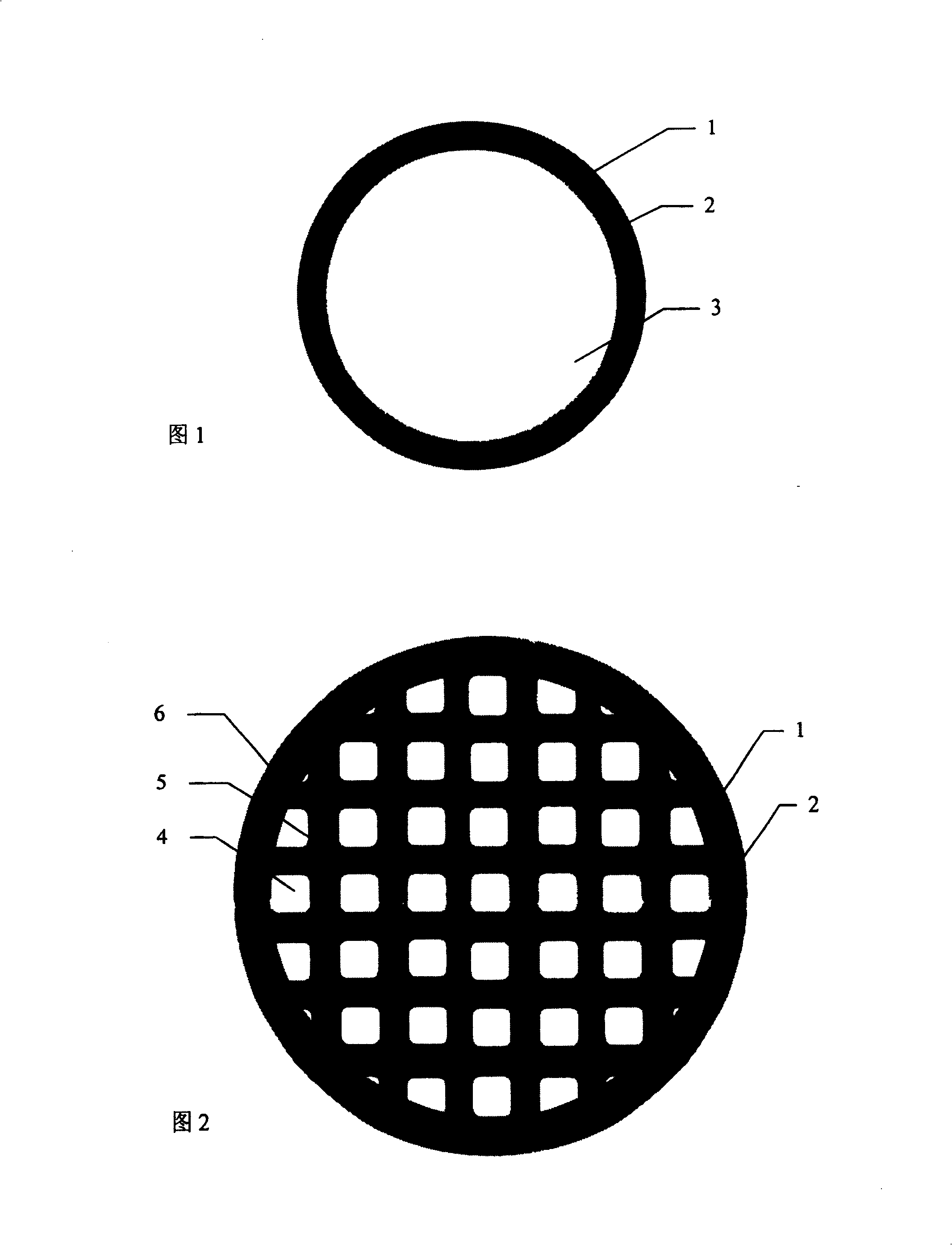
[0007] Embodiment 1: As shown in Figure 2, the multi-core electric injection structure of the vertical cavity surface emitting semiconductor laser with large light exit hole is located in the high aluminum layer in the Bragg reflector; in the annular groove 1 and the oxide confinement region 2 on both sides Several discrete current injection regions 4 are evenly distributed in the enclosed area; these discrete current injection regions 4 are separated by a plurality of linear trenches 5 distributed in the region and oxide confinement regions 6 on both sides; the linear trenches The bottom of 5 is the same as the bottom of annular groove 1, and penetrates the high aluminum layer in the depth direction; the oxide confinement regions 6 on both sides of linear groove 5 are the same as the oxide confinement regions 2 on both sides of annular groove 1 The same, all are at the high aluminum layer level; these linear grooves 5 and the oxide confinement regions 6 on both sides are in th...

Embodiment 2

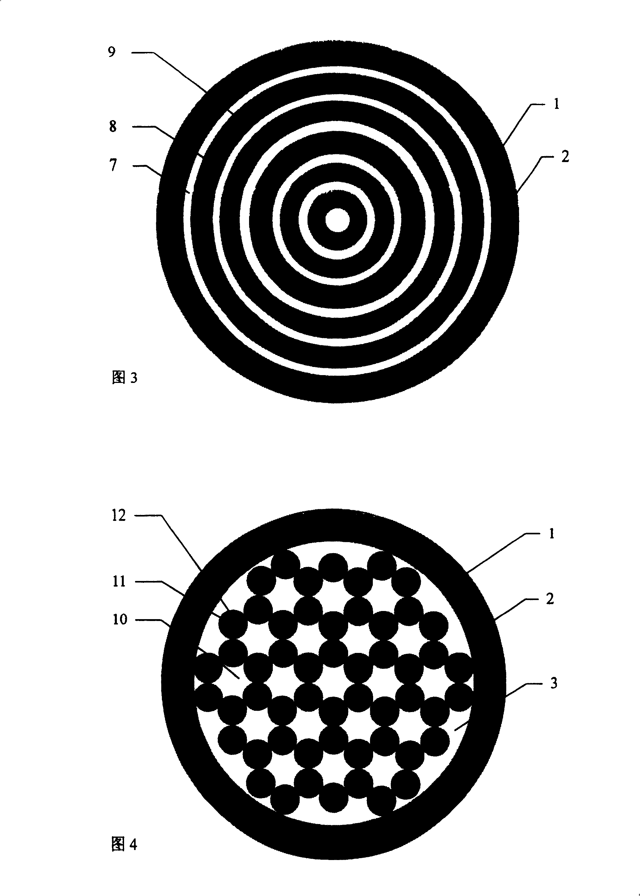
[0008] Embodiment 2; as shown in Figure 3, the multi-core electric injection structure of the vertical cavity surface emitting semiconductor laser with large light exit is located in the high aluminum layer in the Bragg reflector; in the annular groove 1 and the oxide confinement region 2 on both sides A number of discrete current injection regions 7 are evenly distributed in the enclosed area; these discrete current injection regions 7 are separated by a plurality of annular grooves 8 distributed in the region and oxide confinement regions 9 on both sides; the annular grooves The bottom of 8 is the same as the bottom of the annular groove 1, and penetrates the high aluminum layer in the depth direction; same, all at the level of the high aluminum layer; these annular grooves 8 and the oxide confinement regions 9 on both sides are in the shape of concentric rings; the discrete current injection regions 7 are rings with different calibers, and they The rings are evenly distribu...

Embodiment 3

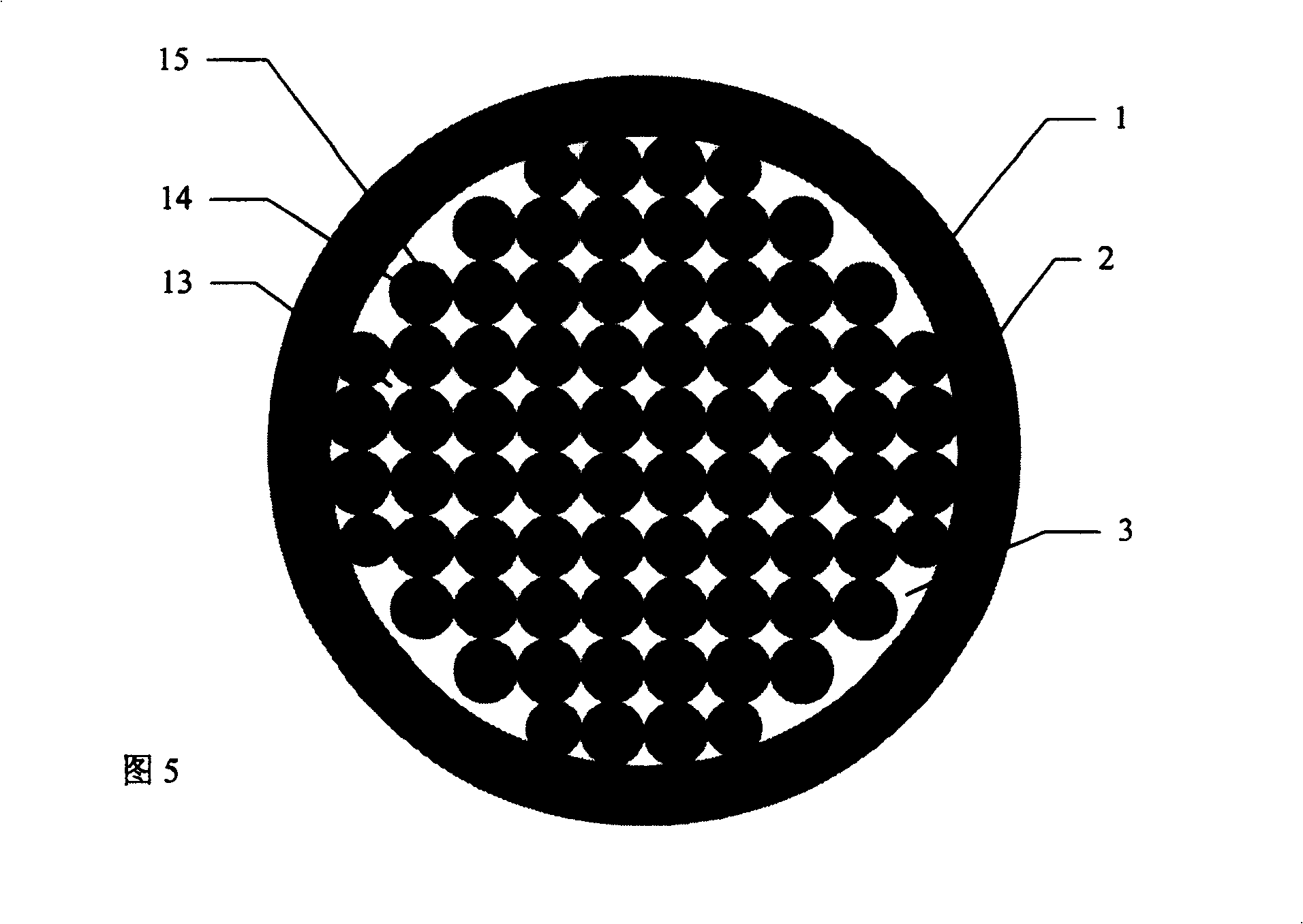
[0009] Embodiment 3: As shown in Figure 4, the multi-core electric injection structure of the vertical cavity surface-emitting semiconductor laser with large light exit hole is located in the high aluminum layer in the Bragg reflector; in the annular groove 1 and the oxide confinement region 2 on both sides Several discrete current injection regions 10 are evenly distributed in the enclosed area 3; these discrete current injection regions 10 are separated by a plurality of holes 11 distributed in the region 3 and oxide confinement regions 12 around them; the bottom of the holes 11 Like the bottom of the annular groove 1, it penetrates through the high aluminum layer in the depth direction; the oxide confinement region 12 around the hole 11 is the same as the oxide confinement region 2 on both sides of the annular groove 1, and is located at the same place. The above-mentioned high-aluminum layer levels are connected to each other; these holes 11 and the oxide confinement region...


PUM


Abstract

A multi - core electricity implanting structure of light outgoing hole vertical cavity surface transmitting semiconductor laser belongs to semiconductor laser technology field. Said invented multi - core electricity implanting structure is located high aluminum layer in Bragg reflection mirror, number of separated current injection zone uniformly distributed in the area enclosed by annular groove and two-sided oxide restricted zone, these separated current injection zone divided by plurality of cavity and surrounding oxide restricted zone, thereby avoiding or reducing adverse effect to device performance service life duo to increasing light outgoing aperture or adopting short burst driving for raising device power. The present invention can be used in semiconductor laser education, research and area of production.

Description

technical field [0001] The invention relates to an electric injection structure of a vertical cavity surface emitting semiconductor laser, belonging to the technical field of semiconductor laser devices. Background technique [0002] In the process of manufacturing a vertical cavity surface emitting semiconductor laser, see Figure 1, an annular groove 1 is etched on the edge of the mesa, and after oxidation, an oxide confinement region 2 is formed on the high aluminum layer in the Bragg reflector near both sides of the groove , and the middle part becomes the light exit hole 3, and the light exit hole 3 of the vertical cavity surface emitting semiconductor laser is also a current injection region. In order to increase the power, the method of enlarging the light exit aperture is generally adopted. Since the light exit aperture of the light exit hole 3 is larger than 10 microns, the carrier aggregation effect is likely to occur, and in order to obtain higher laser power, the...

Claims


Application Information

Patent Timeline
Patent Type & Authority Patents(China)
IPC IPC(8): H01S5/183
Inventor 郝永芹马建立钟景昌赵英杰王晓华乔忠良
Owner CHANGCHUN UNIV OF SCI & TECH
Learn More